
Bush cutting machine

A technology for cutters and shrubs, applied in the direction of harvesters, lawnmowers, cutters, etc., can solve problems such as inspection and adjustment troubles

Inactive Publication Date: 2002-07-17
HONDA MOTOR CO LTD
View PDF0 Cites 7 Cited by
  • Summary
  • Abstract
  • Description
  • Claims
  • Application Information

AI Technical Summary

Problems solved by technology

Moreover, the device requires cumbersome work such as checking and adjusting the stress state of the coupling connected to the rod

Method used


Image

  • Bush cutting machine
  • Bush cutting machine
  • Bush cutting machine

Examples


Embodiment Construction

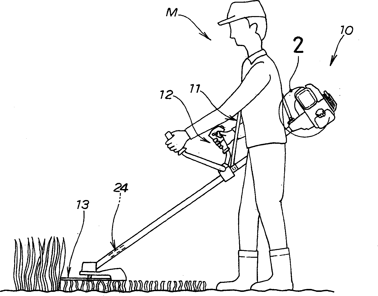
[0015] first reference figure 1 , when cutting bushes, the bush cutter 10 according to the present invention is hung on the shoulders of the operator M through the suspension belt or the shoulder strap 11 while holding the controller 12 firmly. Reference numeral 13 denotes a cutting blade for cutting bushes.

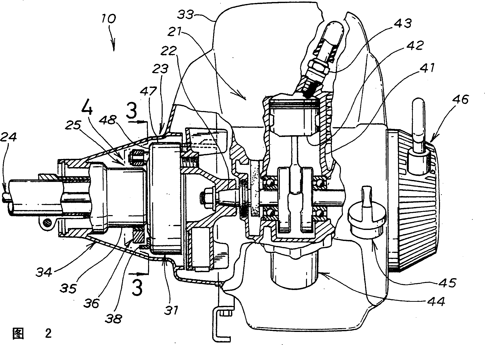
[0016] As shown in FIG. 2, the bush cutter 10 has a motor 21, a centrifugal clutch 23 designed to establish a drive connection when the number of revolutions of a crankshaft 22 serving as an output shaft of the motor 21 exceeds a predetermined value for transfer rotational force or torque to figure 1 The blade drive shaft 24 of the cutting blade 13 shown in , and the automatic braking mechanism 25 .

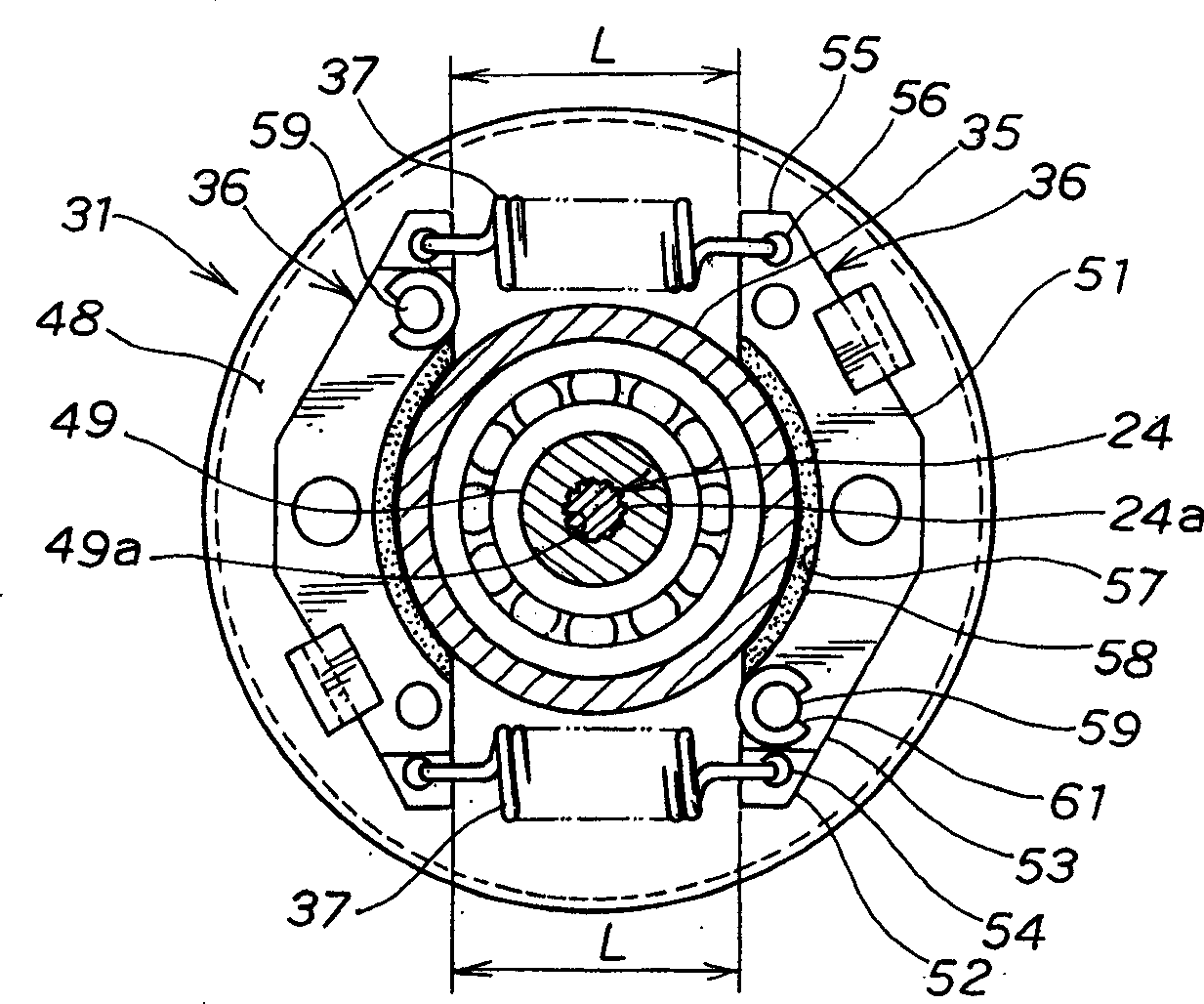
[0017] The centrifugal clutch 23 has a clutch drum 31 mounted on the blade drive shaft 24, a centrifugal pivot member 32 (see Figure 4 ) is arranged on the crankshaft 22 of the motor 21 and placed in the clutch drum 31, and the clutch housing 34 is connected to the moto...


PUM


Abstract

A bush cutting machine (10) including an automatic braking mechanism (25) having a brake drum (35) formed integrally with a clutch case (34) which houses a centrifugal clutch (23). When the number of rotations of a clutch drum (31) decreases, at least two braking members (36) press against the brake drum, whereby the clutch drum stops rotating, and a cutting blade (13) also stops rotating automatically.

Description

technical field [0001] The present invention relates to an improvement in a brake for stopping the rotation of the cutting blade of a bush cutter. Background technique [0002] Brakes for bush cutters have been disclosed, for example in Japanese Utility Model Publication No. SHO-51-53248 entitled "Rotary Knife Stopping Device for Bush Cutters" or in Japanese Utility Model Publication No. SHO-51-53248. .SHO-51-99039 entitled "Safety Devices for Bush Cutters" brakes. [0003] The rotary tool stopper of No. SHO-51-53248 has a pair of brake shoes provided on the outer edge of the driven shaft, mounted as cam discs that press the corresponding brake shoes. When the control of the brake lever is released, the cam disc is driven by the spring to rotate, and the brake shoe is pressed against the outer edge of the driven shaft, thereby stopping the rotation of the rotary tool. However, when stopping the rotation of the rotary cutter, it is troublesome that the above-mentioned rotar...

Claims


Application Information

Patent Timeline
Patent Type & Authority Applications(China)
IPC IPC(8): A01D34/68A01D34/76A01D34/90F16D43/18F16D49/16F16D65/14F16D67/02
CPCF16D67/02F16D49/16F16D2129/043A01D34/90A01D2101/00A01D34/6812A01D34/76
Inventor 平纲贤二郎高野昭人小林隆夫児嶋淳
Owner HONDA MOTOR CO LTD
Learn More