Supercharge Your Innovation With Domain-Expert AI Agents!

Spindle device of machine tool

A technology for machine tool spindles and spindles, which is used in metal processing machinery parts, large fixed members, maintenance and safety accessories, etc. It can solve problems such as adverse effects on human health, sliding wear of cutting fluid, and inability to supply cutting fluid stably.

Inactive Publication Date: 2002-07-17
HORKOS
View PDF0 Cites 7 Cited by
  • Summary
  • Abstract
  • Description
  • Claims
  • Application Information

AI Technical Summary

Problems solved by technology

[0002] When cutting with a machine tool, in order to cool and lubricate the workpiece or cutting tool, or remove chips, a large amount of cutting fluid must be supplied to the processing department, but this has caused many problems: the cutting fluid will pollute the environment and bring harm to human health. Adverse effects, the treatment of waste cutting fluid requires a lot of cost, excessive cooling of the workpiece will shorten the life of the cutting tool, or too much cutting fluid will cause sliding wear when the cutting tool is used for fine cutting. The cutting fluid adheres to the chips, so when the chips are disposed of or reused, the cutting fluid adhering to the chips must be separated
[0009] But adopt above-mentioned existing machine tool, the mist cutting fluid that flows in the central hole of front and rear guide rod parts 16 can flow out in the atmosphere through the gap between parts, causes the waste of cutting fluid
[0010] In addition, since the diameter of the central hole of the front and rear guide rod members 16 is larger than the diameter of the front and rear channels, the mist cutting fluid flowing into the central hole will liquefy, and the liquefaction of the cutting fluid will prevent the cutting fluid from being stably supplied to the The processing part of the workpiece is insensitive to the command to start and stop spraying mist cutting fluid from the tip of the cutting tool

Method used


Image

  • Spindle device of machine tool
  • Spindle device of machine tool
  • Spindle device of machine tool

Examples


Embodiment Construction

[0021] The present invention will be described below with reference to the accompanying drawings.

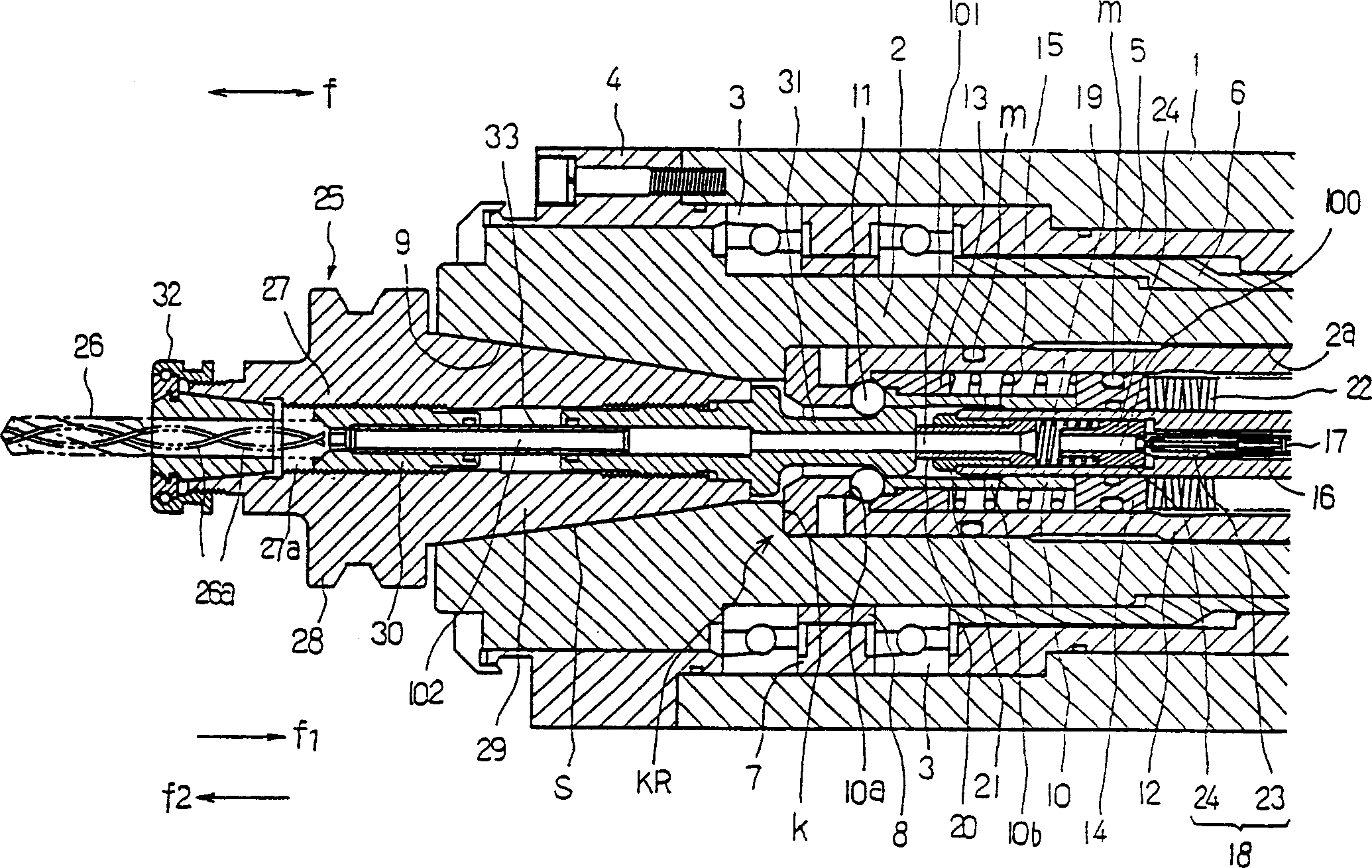
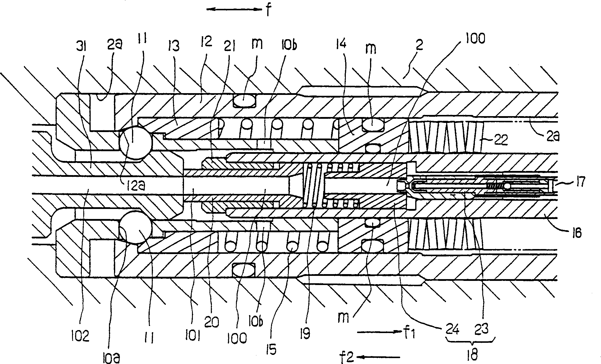
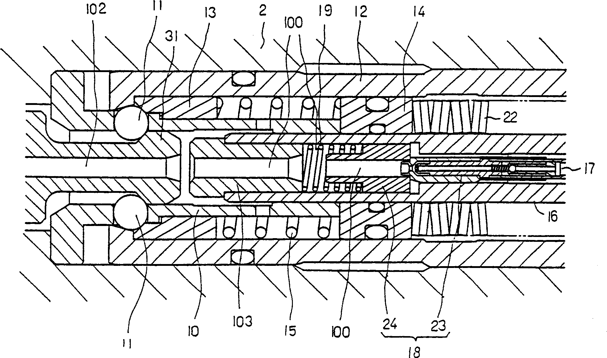
[0022] In the accompanying drawings, 1 is a main shaft support of the machine tool, 2 is a main shaft, and the main shaft is rotatably supported by a bearing 3 . 4 is an annular part that limits the displacement of the bearing 3 or the front and rear direction f of the main shaft 2, and is fixed on the front end surface of the main shaft support 1 with bolts. Liners 5, 6, 7, 8 are arranged between the main shaft support 1 and the main shaft 2, and between the bearings 3, 3.

[0023] A locking device KR is formed at the central portion of the above-mentioned main shaft 2 as described below.

[0024] That is, the tip end portion of the inner hole 2 a formed in the center portion of the main shaft 2 serves as the tapered fitting hole 9 . The cartridge 10 is inserted into the back of the inner hole 2a, and its front end is supported by the stepped portion k to be in a fixed state....


PUM


Abstract

A spindle device of a machine tool stably injecting spray coolant from the tip of a tool (26) in a tool holder (25) and suppressing a waste of the spray coolant, wherein the tool holder (25) is fixed to the tip part of a spindle (2) mechanically detachably through clamp means (KR), an extension passage (101) is formed in the state that an in-spindle spray coolant passage (100) formed in the center part of the spindle (2) is extended forward (f2), and the in-spindle spray coolant passage (100) is formed to communicate with an in-holder spray coolant passage (102) formed in the center part of the tool holder (25) through the extension passage (101).

Description

technical field [0001] The invention relates to a machine tool spindle device capable of spraying mist cutting fluid from the top of a cutting tool. Background technique [0002] When cutting with a machine tool, in order to cool and lubricate the workpiece or cutting tool, or remove chips, a large amount of cutting fluid must be supplied to the processing department, but this has caused many problems: the cutting fluid will pollute the environment and bring harm to human health. Adverse effects, the treatment of waste cutting fluid requires a lot of cost, excessive cooling of the workpiece will shorten the life of the cutting tool, or too much cutting fluid will cause sliding wear when the cutting tool is used for fine cutting. Since the cutting fluid adheres to the chips, it is necessary to separate the cutting fluid adhered to the chips when disposing of the chips or reusing them. [0003] In order to solve these problems, in recent years, a machine tool that makes a ver...

Claims


Application Information

Patent Timeline
IPC IPC(8): B23Q1/00B23Q1/70B23Q11/10
CPCB23Q11/1015Y10T408/455Y10T409/304032Y10T408/45B23Q1/70B23Q11/10
Inventor 菅田泰介濑尾义秀小林隆志
Owner HORKOS
Features
  • R&D
  • Intellectual Property
  • Life Sciences
  • Materials
  • Tech Scout
  • Unparalleled Data Quality
  • Higher Quality Content
  • 60% Fewer Hallucinations
Learn More