Asymmetrical bridge type DC/DC converter

An asymmetric, converter technology, applied in the improved circuit design and structure, in the field of asymmetric full-bridge DC/DC converters, which can solve the problems of transformer design problems, non-linear control of output voltage switch duty cycle, etc.

Inactive Publication Date: 2002-09-25
DELTA ELECTRONICS INC
View PDF0 Cites 5 Cited by
  • Summary
  • Abstract
  • Description
  • Claims
  • Application Information

AI Technical Summary

Problems solved by technology

But the magnetizing current has a DC bias, which poses a problem for the transformer design
Another problem wit...

Method used


Image

  • Asymmetrical bridge type DC/DC converter
  • Asymmetrical bridge type DC/DC converter
  • Asymmetrical bridge type DC/DC converter

Examples


Embodiment Construction

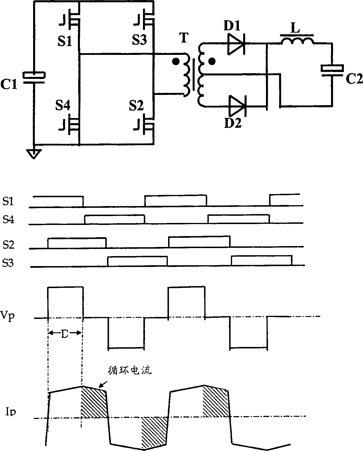
[0035] A preferred embodiment of the present invention is shown in Figure 5 . The asymmetric full bridge DC / DC converter comprises an asymmetric full bridge with first, second, third and fourth switching devices (hereinafter referred to as switches S1, S2, S3, S4) and a compensation capacitor Cp, a transformer It has a primary side winding and a secondary side winding, and a rectifier circuit connected to the secondary side of the transformer.

[0036] S1 and S4 form a branch line of the full bridge; S2 and S3 and Cp connected in series form another branch line of the full bridge. The primary winding of the transformer is connected to the center point of these two legs. S1 and S2 are the main switches, which conduct the reflected output current and the magnetizing current. S3 and S4 are auxiliary switches which only conduct magnetizing current.

[0037]The main switches S1, S2 are turned on and off synchronously, and the auxiliary switches S3, S4 are also turned on and of...


PUM


Abstract

The present invention provides an asymmetric full-bridge DC/DC converter, which includes an asymmetric full-bridge circuit, the full-bridge circuit includes two main switches and two auxiliary switches, and a capacitor is connected in series with the branch circuits of these auxiliary switches , and a transformer having a primary winding and a secondary winding. The primary winding of the transformer is connected to the common point of each branch of the full bridge. A rectifier circuit is connected to the secondary winding of the transformer to obtain a DC voltage output. In operation, an asymmetric control method is applied to these main and auxiliary switches. The main switch and the auxiliary switch are turned on and off complementary. The linear control characteristic of the output voltage to the duty ratio of the switch and the optimal return of the transformer core are achieved by the present invention.

Description

technical field [0001] The present invention generally relates to power supply systems involving DC / DC conversion operations, and more particularly, the present invention relates to an improved circuit design and construction having an asymmetric full-bridge DC / DC conversion with a wide input voltage range device. Background technique [0002] The prior art DC / DC converter design and fabrication is still limited by the lack of an optimal circuit for high input voltage and wide input range operation. [0003] figure 1 The structure and key operating waveforms of the single-ended forward DC / DC converter are shown. In such a converter, only one switch S1 is used in the primary side of the transformer. When the switch S1 is turned on, the primary winding of the transformer is connected to the input voltage Vin, and the energy is transmitted from the input power to the load through the transformer coupling. When the switch S1 is turned off, the primary winding of the transfor...

Claims


Application Information

Patent Timeline
IPC IPC(8): H02M3/335H02M3/337H02M7/5387
CPCH02M3/3372H02M3/33573
Inventor 章进法黄贵松顾亦磊
Owner DELTA ELECTRONICS INC
Why Eureka
Try Eureka