Indicator

A technology for display devices and display parts, applied in lighting devices, static indicators, cathode ray tube indicators, etc., capable of solving problems such as power consumption and current value increase

Inactive Publication Date: 2002-10-02
SANYO ELECTRIC CO LTD
View PDF0 Cites 7 Cited by
  • Summary
  • Abstract
  • Description
  • Claims
  • Application Information

AI Technical Summary

Problems solved by technology

[0007] However, with the increase of electronic devices that strive for low power consumption, such as mobile phone displays, when an organic EL display device is used as the display of such devices, it is necessary to control its power consumption, especially to suppress the maximum power consumption.
In addition, since the organic EL element generates heat by current driving, even if the voltage of the power supply line VL is constant, the value of the current flowing through the organic EL element may increase, and unnecessary power consumption may be caused.

Method used


Image

  • Indicator
  • Indicator
  • Indicator

Examples


Embodiment Construction

[0024] The preferred embodiment of the present invention will be described below with accompanying drawings.

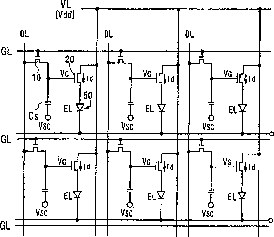
[0025] figure 1 is a diagram showing a circuit configuration of a display portion of an active matrix type EL display device with m rows and n columns according to an embodiment of the present invention, basically the same as the above-mentioned Figure 7 same. Each pixel of the plurality of pixels provided in the display section is configured near a region surrounded by gate lines GL extending in the row direction, data lines DL and power supply lines VL extending in the column direction, and has an organic EL element 50, a switching TFT (first TFT) 10, an element driving TFT (second TFT) 20, and a holding capacity Cs. The gate of the first TFT 10 is turned on by receiving a gate signal, and the storage capacitor Cs connected between the first TFT 10 and the second TFT 20 holds the data signal from the data line DL. The second TFT 20 is provided between the power ...


PUM


Abstract

Controls the power consumption of display devices with current-driven elements such as EL. The current control circuit 300 is provided between the power supply circuit 200 and the power supply line VL that supplies driving current to the organic EL elements 50 provided in the respective light emitting elements of the display panel, and detects the amount of current flowing from the power supply circuit 200 through the power supply line VL. When the flow rate increases, the power supply voltage Vdd applied to the power supply line VL is lowered, thereby reducing the current flowing through the organic EL element 50 . Alternatively, the contrast and luminance level of display data supplied to each EL element 50 are controlled according to the detected current amount, and the contrast and luminance level are lowered to limit the current flowing through the organic EL element 50 when the current amount increases. In this way, the amount of current flowing through the organic EL element 50 can be limited, and the power consumption of the display device will not be too large.

Description

technical field [0001] The present invention relates to a display device having a current-driven light-emitting element such as an organic electroluminescent (hereinafter referred to as EL) element. Background technique [0002] The EL display device using the EL element of the current-driven light-emitting element as each pixel is a self-luminous device, and has the advantages of thinness and low power consumption. As a display device replacing a liquid crystal display device (LCD) and a CRT display device, etc. attention, and its research is ongoing. [0003] Among them, an active matrix EL display device in which switching elements such as thin film transistors (TFTs) for individually controlling EL elements are provided in each pixel to control EL elements pixel by pixel is expected to appear as a high-precision display device. [0004] Figure 7 Represents the circuit structure of a single pixel in an active matrix EL display device with m rows and n columns. On the s...

Claims


Application Information

Patent Timeline
Patent Type & Authority Applications(China)
IPC IPC(8): H05B44/00G09G3/20G09G3/30G09G3/32G09G5/04H01L51/50
CPCG09G3/3233G09G5/04G09G2300/0842G09G2320/066G09G2330/021G09G2330/028G09G2330/04G09G2370/04G09G3/30
Inventor 古宫直明
Owner SANYO ELECTRIC CO LTD
Why Eureka
Try Eureka