Anti-reflection coatings and coated articles

An anti-reflection and product technology, which is applied in the direction of coating, layered products, metal material coating technology, etc., can solve the problem of reducing the amount of reflected light

Inactive Publication Date: 2002-10-02
彼得・D・霍兰 +1
View PDF0 Cites 7 Cited by
  • Summary
  • Abstract
  • Description
  • Claims
  • Application Information

AI Technical Summary

Problems solved by technology

The problem is therefore to choose a range of layer thicknesses that minimize or greatly reduce the amount of reflected light that is perceived by the human visual system over the entire range of relevant angles and wavelengths

Method used


Image

  • Anti-reflection coatings and coated articles
  • Anti-reflection coatings and coated articles
  • Anti-reflection coatings and coated articles

Examples


example 1

[0052] According to the invention, the perceived reflectance F is found from all combinations of coating thicknesses, and the set of thicknesses that minimizes F is chosen. Starting with the glass:PrO:TiO:MgF system described above, this calculation was done and calculated a minimum perceived reflectance of 104 which is 18% of the uncoated product and a drop of 35% from the textbook coating. %. The absolute minima of perceived reflectance for these materials (shown in Figure 6) correspond to the following physical thicknesses: 100 nm of PrO, 25 nm of TiO and 87 nm of MgF.

example 2-19

[0055] The thickness combinations listed in Table I do not exclude other combinations with F-values ​​within 25% (or other desired lower percentage) of the minimum value of 104. However, after examining the 16000+ permutations, it is found that only examples 1-13 meet this judgment condition.

[0056] Those of ordinary skill in the art know that using linear algebra and calculus can solve Equation 7 (F, F min , 1.25F min , or any other desired value and range of F). For an alternative to performing manual calculations, linear algebra software can be used. Non-limiting examples of such software include Mathematic (Wolfram Research, Champaign-Urbana, IL), Matlab (TheMathWorks, Inc., Natick, MA), Macsyma (Macsyma Inc., Arlington, MA), and MaPle (Waterloo MaPle, Inc. ., Waterloo, Ontario, Canada). Calculation and analysis of F can also be performed using electronic data software such as Excel (Microsoft, Redmond, WA) and Lotus 1-2-3 (Lotus Development Corp., Cambridge MA)...

example 20-30

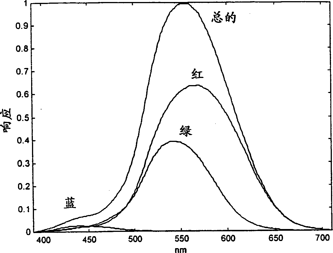
[0067] A second embodiment of the AR coated article of the present invention is a computer monitor or video screen having a glass surface. Anti-reflection coatings are required for these articles because overhead or window illumination produces reflected images that impair the visibility of the image projected onto the display screen. The photopic response S(λ) of the observer is as follows figure 1 shown. However, the angular components of S(λ, θ) are substantially different from those of glasses. Assuming top lighting in a specific working environment and using a simple geometry, the sample S(λ, θ) is as Figure 12 shown. The perceived reflectance of the uncoated screen was 717, while noting that the textbook PrO:TiO:MgF coating was 258, or 36% of the uncoated display. Using the method described above, it was found that F was reduced to 191 with minimum values ​​(26.6% of the uncoated display) at layer thicknesses of 60 nm of PrO, 80 nm of TiO and 120 nm of MgF. Indicat...


PUM

PropertyMeasurementUnit
thicknessaaaaaaaaaa

Abstract

A transparent or translucent coated article, comprising an optical substrate and one or more layers of anti-reflection material coated on at least a portion of the optical substrate, characterized in that said one or more layers having a thickness such that the article simultaneously has (i) a color, when viewed at a specified angle or angles, under a specified illumination, that is perceived to lie within a specified volume element of color space defined by the color's CIE chromaticity coordinates, and (ii) a perceived reflectance F=ˆ«ˆ«S(»,¸)R(»,¸)d»d¸ that is less than or equal to 1.25F min , wherein » is wavelength, ¸ is incident angle, S(»,¸) is the human sensitivity function as a function of wavelength and incident angle, R(»,¸) is an average of p- and s-polarized reflectance, and F min is perceived reflectance minimized within the constraints imposed by said chromaticity coordinates.

Description

Background of the invention [0001] The present invention generally relates to improving the transmission of light through optical materials, such as eyeglasses, while reducing reflections of stray light from the optical materials that cause glare. The invention also relates to controlling the perceived color of light reflected from the surface of an optical material. [0002] All uncoated optically transparent materials reflect a portion of incident light. The amount of reflection varies with the wavelength, polarization and angle of incidence of the light and with the wavelength-dependent refractive index n of the material. Fresnel reflection is described by Maxwell's equations for electromagnetic radiation implemented in the field of optics, and is documented in Principles of Optics (Optical Principles) published by M.Born and E.Wolf in New York Pergammon Press in 1980 . It is well known that a layer of transmissive material having a different refractive index than the su...

Claims


Application Information

Patent Timeline
Patent Type & Authority Applications(China)
IPC IPC(8): G02C7/02B32B7/02C03C17/22C03C17/25C03C17/30C03C17/32C03C17/34C03C17/36C03C17/42C23C16/52G02B1/11
CPCC03C17/225C03C17/256C03C17/30C03C17/32C03C17/328C03C17/34C03C17/42C03C2217/734C23C16/52G02B1/11G02B1/111
Inventor 彼得·D·霍兰B·文森特·穆科
Owner 彼得・D・霍兰
Why Eureka
Try Eureka