Precise workstable structure for array IC photoetching system

A technology of integrated circuits and lithography systems, which is applied in the field of precision workbench structures and can solve problems such as difficulty in realizing workbench synchronization.

Inactive Publication Date: 2002-10-16
TSINGHUA UNIV
View PDF0 Cites 7 Cited by
  • Summary
  • Abstract
  • Description
  • Claims
  • Application Information

AI Technical Summary

Problems solved by technology

Large strokes and high operating speeds, as well as the synchronization of

Method used


Image

  • Precise workstable structure for array IC photoetching system
  • Precise workstable structure for array IC photoetching system
  • Precise workstable structure for array IC photoetching system

Examples


Embodiment Construction

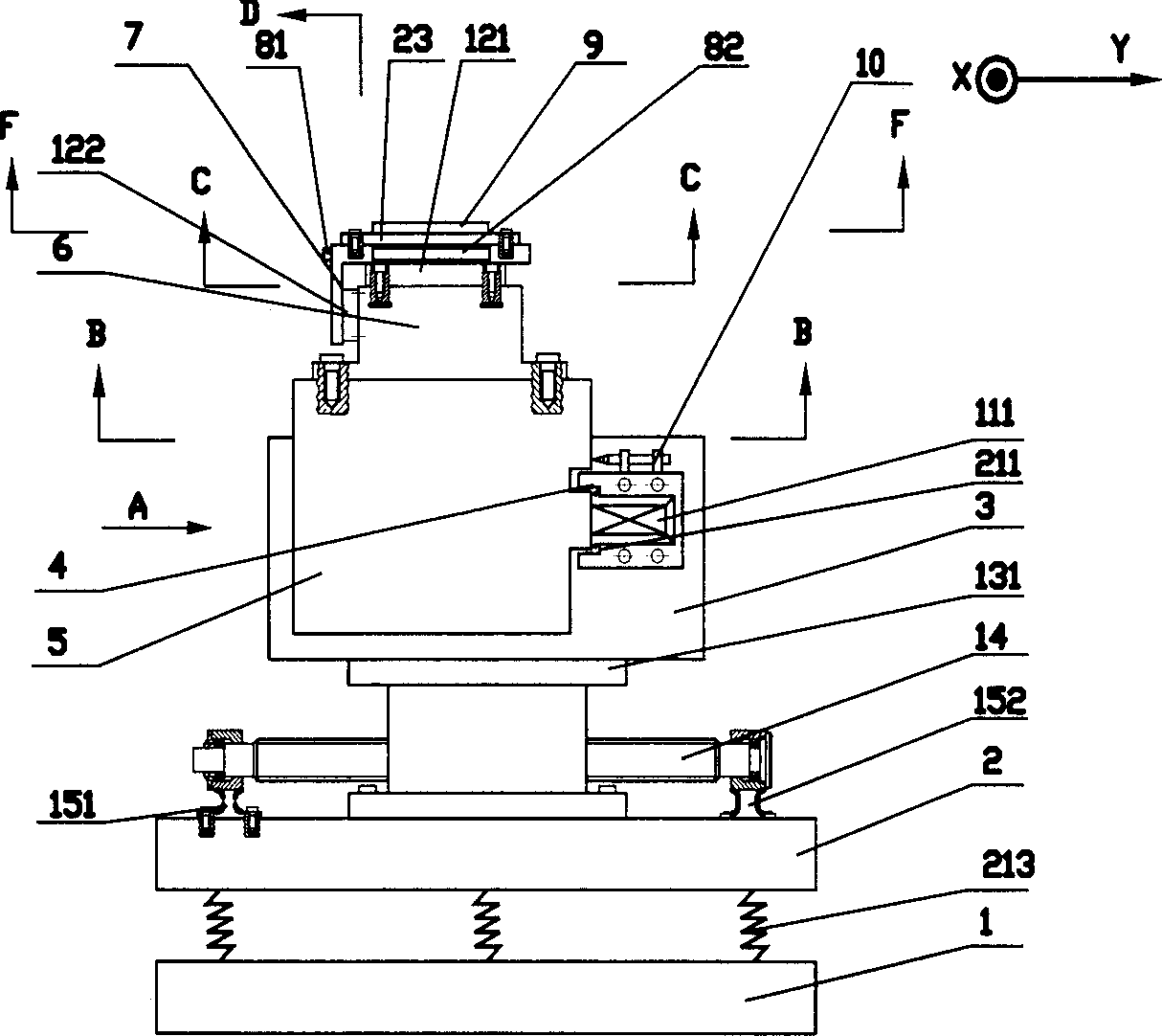
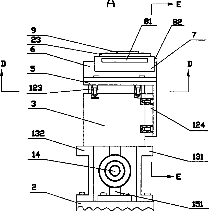
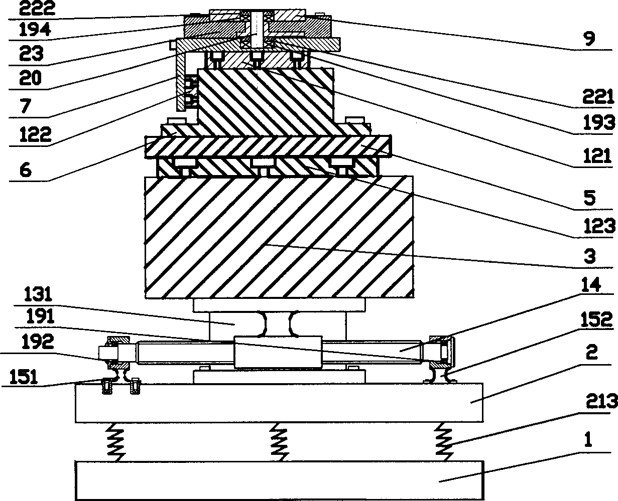
[0015] please see Figure 1 to Figure 9 . 1 is an anti-vibration table, and the 2nd is a workbench base, which links to each other with the anti-vibration table 1 with a spring 213. The 14th, ball screw, it is connected with workbench base 2 screws through support members 151,152. 131,132 are support rails connected with workbench base 2 screws. The Y-direction aerostatic guide rail 3 is connected with the support guide rails 131 and 132 . The Y-direction piezoelectric ceramic frame 4 is fixed on the Y-direction aerostatic guide rail 3 with screws. One end is fixed on its inner bottom surface to the Y-direction piezoelectric ceramic body 111 of T-shaped Y-direction motion workbench 5 in Y direction, and 161 is its electrode; To the inductance micrometer, the Y-direction motion table 5 is connected with the Y-direction piezoelectric ceramic frame 4 with a spring. The T-shaped Y-shaped motion table 5 is in contact with the T-shaped guide rail air cushions 123, 124 on the Y-...


PUM


Abstract

The present invention belongs to the integrated circuit manufacturing superfine engineering. The precise work table includes micro turntable, turntable seat coaxially connected to the turntable, turntable driving support, small X direction table with X and Y direction mirror and capable of reciprocating in X direction, hydrostatic X direction air guide, Y direction stable, hydrostatic Y directionair guide, Y direction micro mechanism, rolling screw bolt to drive the hydrostatic Y direction air guide and elastic shock-proof worktable. The micro mechanism for the turntable driving support and the Y direction stable are driven with piezoelectrics; and both the X direction table and the Y direction stable are T-shaped. The present invention can ensure both scanning precision and photoetchingefficiency.

Description

technical field [0001] The invention discloses a precision workbench structure in an array type integrated circuit photoetching system, which belongs to the technical field of micro engineering in integrated circuit manufacturing. Background technique [0002] In the existing integrated circuit lithography system, the workbench is divided into a workpiece stage for clamping a silicon wafer and a wafer stage for clamping a mask. Both tables must have high-speed movement in the X and Y directions, and the stroke is relatively large. The X and Y strokes of the workpiece table for clamping silicon wafers are determined according to the size of the silicon wafers to be processed. When processing a 10-inch wafer, the stroke is 300mm×300mm, and the stroke of the wafer holder for the mask is determined according to the size of the silicon wafers. It depends on the reduction ratio of the mask projection. When the reduction ratio of processing a 10-inch wafer is 4:1, the stroke is 10...

Claims


Application Information

Patent Timeline
IPC IPC(8): G03F7/20
Inventor 徐端颐范晓冬齐国生钱坤蒋培军麦雪松
Owner TSINGHUA UNIV
Why Eureka
Try Eureka