Process for unloading catalyst from petrochemical equipment
A technology of petrochemical devices and catalysts, which is applied in chemical instruments and methods, methods for chemically changing substances by using atmospheric pressure, and the petroleum industry, and can solve problems that may endanger the health of workers
- Summary
- Abstract
- Description
- Claims
- Application Information
AI Technical Summary
Problems solved by technology
Method used
Image
Examples
Embodiment 1
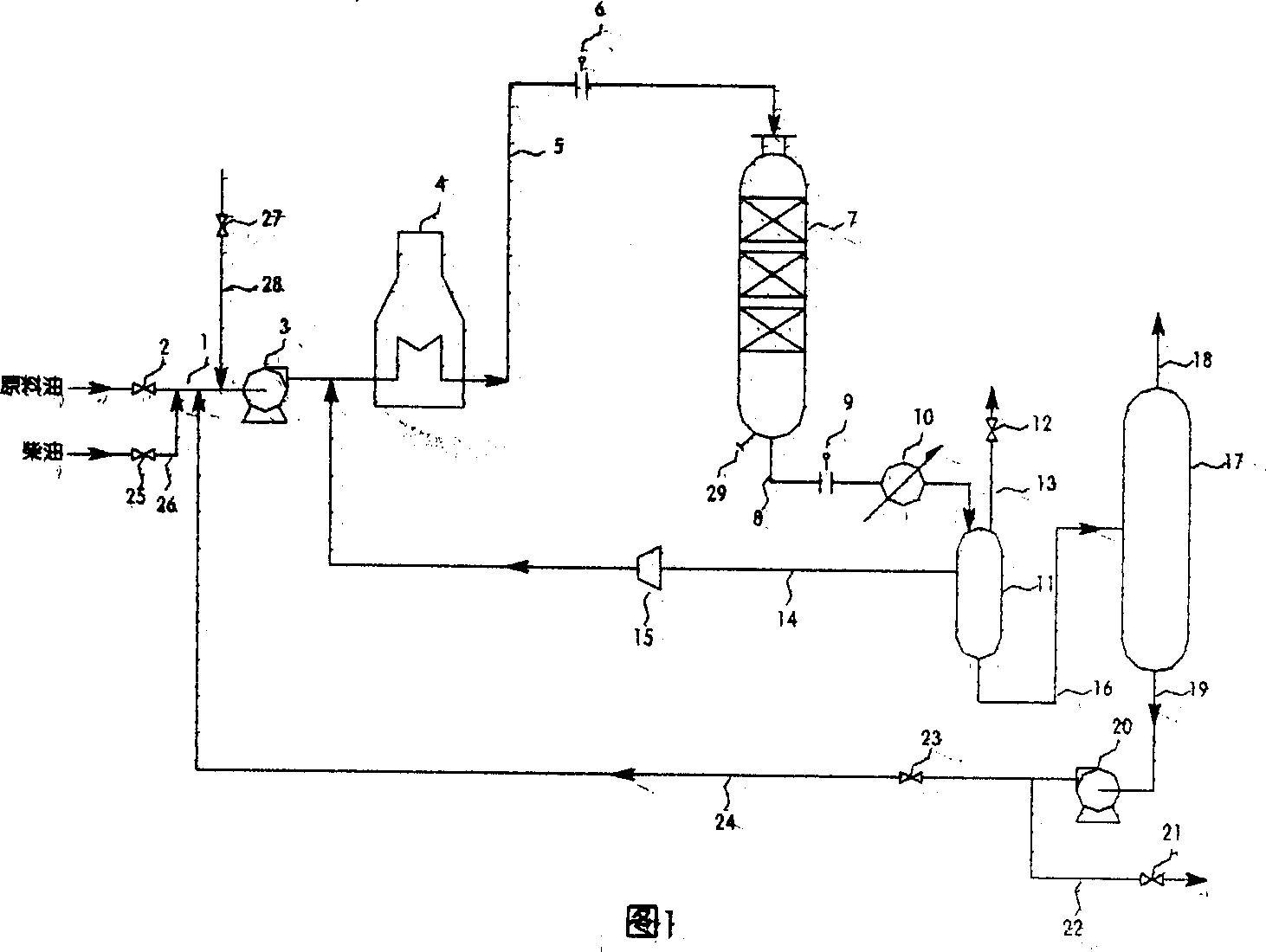
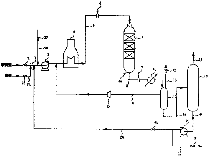
[0018] Fig. 1 is a schematic diagram of the film-forming method on the surface of an oil agent circulation catalyst. There are valves 2 and pumps 3 on the raw oil pipeline 1 . At the outlet of the pump, there is a heating furnace 4. The heating furnace 4 and the reaction tower 7 are connected by a pipeline 5, and there is a flange 6 on the pipeline, which can be inserted into a blind plate. The reaction tower 7 is connected with the cooler 10 and the gas-liquid separator 11 through the pipeline 8, and there is a flange 9 on the pipeline 8, which can be inserted into a blind plate. The top of the gas-liquid separator 11 is connected with the valve 12 through the pipeline 13, so that the tail gas is discharged to other equipment. The hydrogen in the gas-liquid separator 11 is pressurized by the gas compressor 15 and sent to the heating furnace 4 through the pipeline 14 . The liquid in the gas-liquid separator 11 is sent to a distillation column 17 through a line 16 . The top...
Embodiment 2
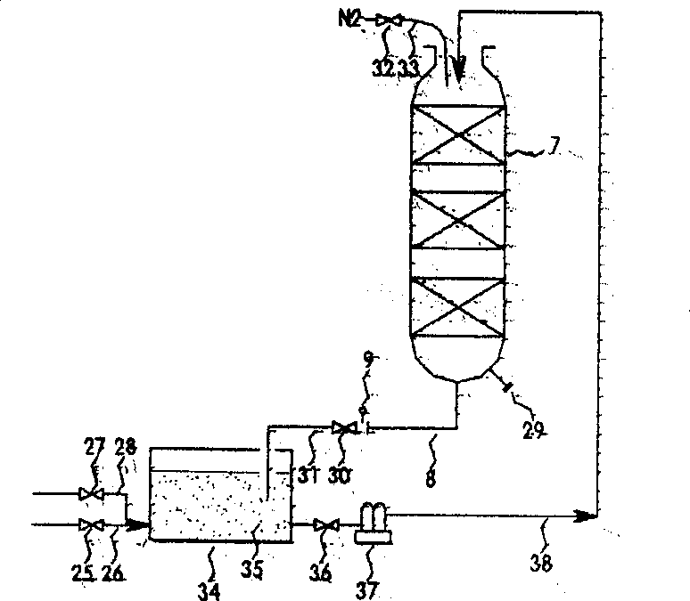
[0021] figure 2 It is a schematic diagram of the film-forming method on the catalyst surface soaked in oil. Open valve 25 and lead solvent oil and fuel oil into storage tank 34 through pipeline 26. Open the valve 27 and inject the film-forming agent into the solvent oil in the storage tank 34 through the pipeline 28, and prepare the oil agent 35 in advance. Solvents and film formers are simply stirred at room temperature.
[0022] After the device is stopped according to the general shutdown procedure, a valve 30 is installed at the flange 9 in the pipeline 8 at the bottom of the reaction tower 7, and the pipeline 31 is connected to the storage tank 34. Open the valve 36, and the oil agent 35 is pressed into the reaction tower 7 through the pipeline 38 with the pump 37 until the oil agent immerses the catalyst in the tower. In order to prevent air from entering the reaction tower, while injecting the oil agent 35 into the reaction tower, open the valve 32 and flush nitrogen...
PUM
 Abstract
Description
Claims
Application Information
 - R&D
- Intellectual Property
- Life Sciences
- Materials
- Tech Scout
- Unparalleled Data Quality
- Higher Quality Content
- 60% Fewer Hallucinations
Browse by: Latest US Patents, China's latest patents, Technical Efficacy Thesaurus, Application Domain, Technology Topic, Popular Technical Reports.
© 2025 PatSnap. All rights reserved.Legal|Privacy policy|Modern Slavery Act Transparency Statement|Sitemap|About US| Contact US: help@patsnap.com


