Screen printing device and screen printing method

A technology of screen printing and masking plate, which is applied to screen printing machines, printing machines, printing machines, etc., and can solve problems such as unstable printing conditions and quantity fluctuations

Inactive Publication Date: 2002-11-20
PANASONIC CORP
View PDF3 Cites 15 Cited by
  • Summary
  • Abstract
  • Description
  • Claims
  • Application Information

AI Technical Summary

Problems solved by technology

However, if the surface of the substrate has curvature or undulations, the angle of attack will vary according to the degree of curvature of the substrate surface
In that case, printing conditions become unstable and fluctuate the amount of solder paste delivered by the squeegee head

Method used


Image

  • Screen printing device and screen printing method
  • Screen printing device and screen printing method
  • Screen printing device and screen printing method

Examples


no. 1 example

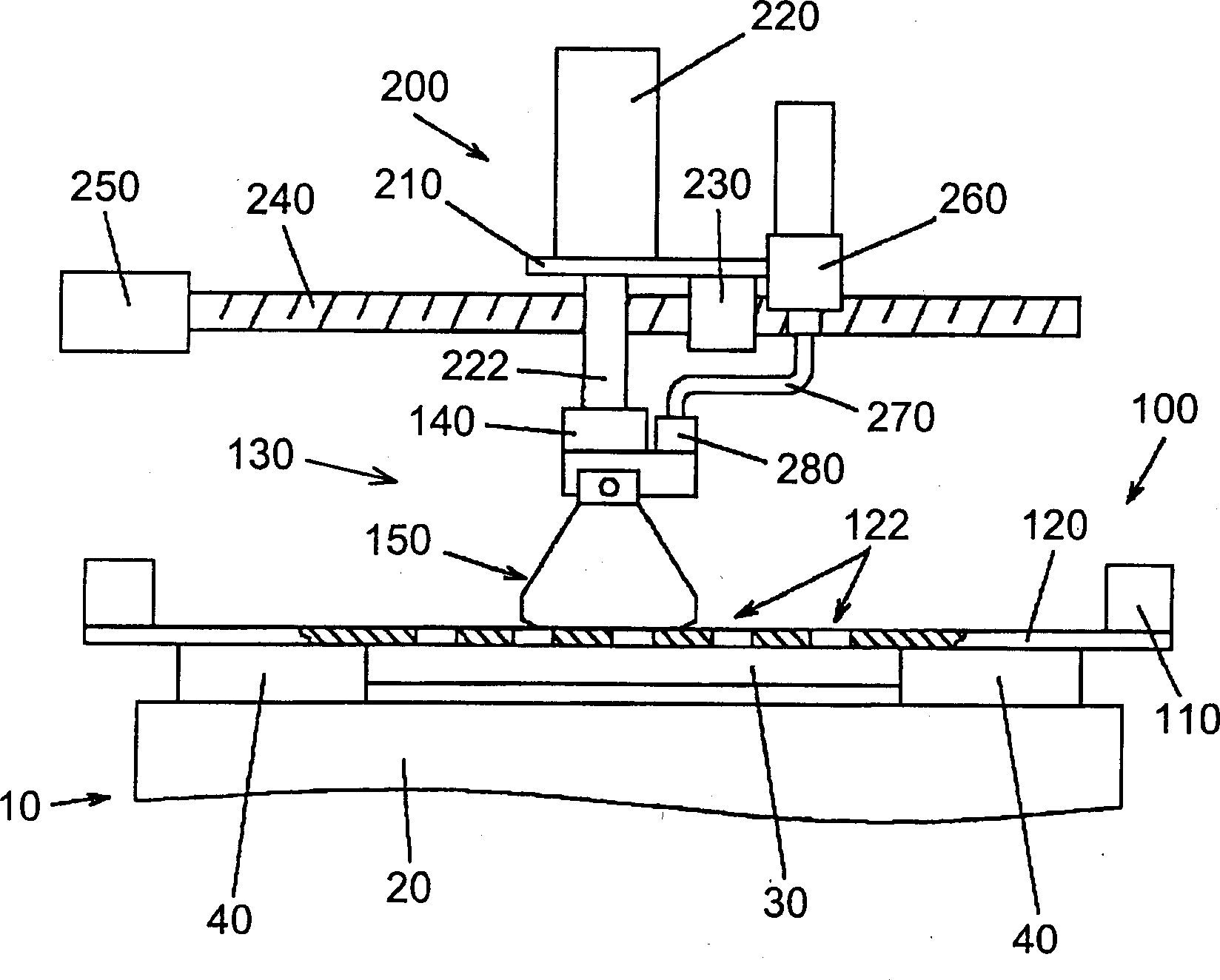
[0020] See figure 1 and 2 , the substrate positioner 10 includes a substrate holder 20 disposed on a movable workbench (not shown in the figure) and a clip 40 connected to the substrate holder 20 . The clamp 40 holds the substrate 30 to be printed, and positions the substrate horizontally and vertically by driving the movable table.

[0021] The screen mask 100 includes a shielding plate 120 attached to the holder 110 and disposed above the substrate positioner 10 . The shielding plate 120 has a plurality of pattern holes 122 corresponding to the positions to be printed on the substrate 30 to form printing patterns on the substrate 30 .

[0022] The squeegee head 130 is located above the screen cover 100 so that the squeegee head 130 can move up and down by means of the head lifter 200 . The head lifter 200 is equipped with a cylinder 220 provided on the plate 210 .

[0023] The squeegee head 130 is connected to the lower end of the rod 222 of the cylinder 220 . The squee...

no. 2 example

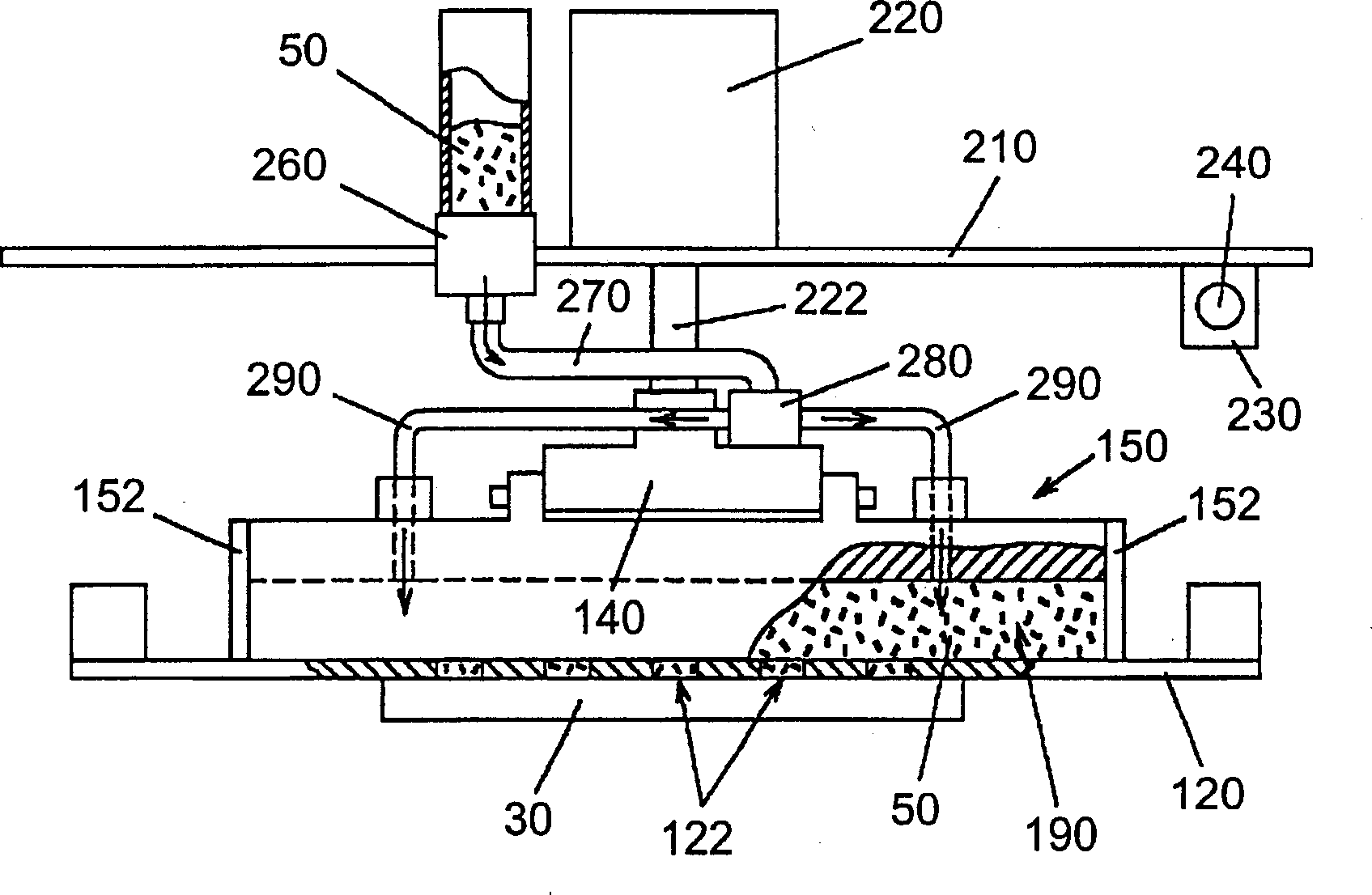
[0045] Conventional screen printing devices generally control the temperature of solder by blowing hot air to the solder placed on a shielding plate. According to such a conventional screen printing apparatus, since the solvent in the solder is easily volatilized, there is a disadvantage that the solder hardens in a short time.

[0046] Such as Figure 6 As shown, the second embodiment is an arrangement of the first embodiment to control the temperature of the solder 50 using a temperature controller in the paste chamber 190 . In the second embodiment, substantially the same components as those of the first embodiment are given the same reference numerals.

[0047] According to the second embodiment, the temperature of a part of the squeegee device 150 is controlled using a temperature controller such as heaters 300 , 302 and 304 provided on the holding plate 182 in order to control the temperature of the solder 50 . In the same way will Figure 6 The same heater not shown ...


PUM


Abstract

A method and device for screen printing, which can keep the angle of attack between a squeegee and a masking plate constant, regardless of the surface condition of the masking plate. A holder rotatably supports a squeegee head (including a pair of squeegee rollers) relative to a horizontal axis, the horizontal axis being at right angles to the rolling direction of the squeegee. A pneumatic cylinder pushes the rotatably supported squeegee head against the shielding plate. Therefore, even if the substrate has a curved portion, the attack angle can be kept constant to improve the printing quality.

Description

[0001] Related applications for reference [0002] This application is based on and claims the benefit of priority from Japanese Patent Application No. 2001-113693 filed on April 12, 2001, the contents of which are incorporated herein by reference. technical field [0003] The present invention relates to a screen printing apparatus for printing paste (such as solder paste or conductive paste) on a substrate, and a method of screen printing. Background technique [0004] In the process of mounting electronic components, a screen printing that prints a paste (eg, cream solder or conductive paste) on a substrate is used. According to screen printing, a masking plate having patterned holes corresponding to positions to be printed is placed over the substrate, and paste is printed on the substrate through the patterned holes using a squeegee method. [0005] According to conventional squeegee rolling methods or devices, such as those disclosed in U.S. Patent No. 5,996,487, publ...

Claims


Application Information

Patent Timeline
Patent Type & Authority Applications(China)
IPC IPC(8): B41F15/44B41F15/08B41F15/40B41F15/46H05K3/12H05K3/34
CPCB41F15/40B41F15/46H05K3/1233H05K2203/0126
Inventor 山崎公幸阿部成孝宫原清一友松道范
Owner PANASONIC CORP
Why Eureka
Try Eureka