

Directional coupler and directional coupling method
A technology of directional coupler and electromagnetic coupling, which is applied in the direction of waveguide devices, electrical components, connecting devices, etc., can solve the problems that the desired suppression amount of the filter cannot be obtained, and the characteristics of the capacitor or parallel resonator of the low-pass filter cannot be realized.
- Summary
- Abstract
- Description
- Claims
- Application Information
AI Technical Summary
Problems solved by technology
Method used
Image

Examples
Embodiment 1
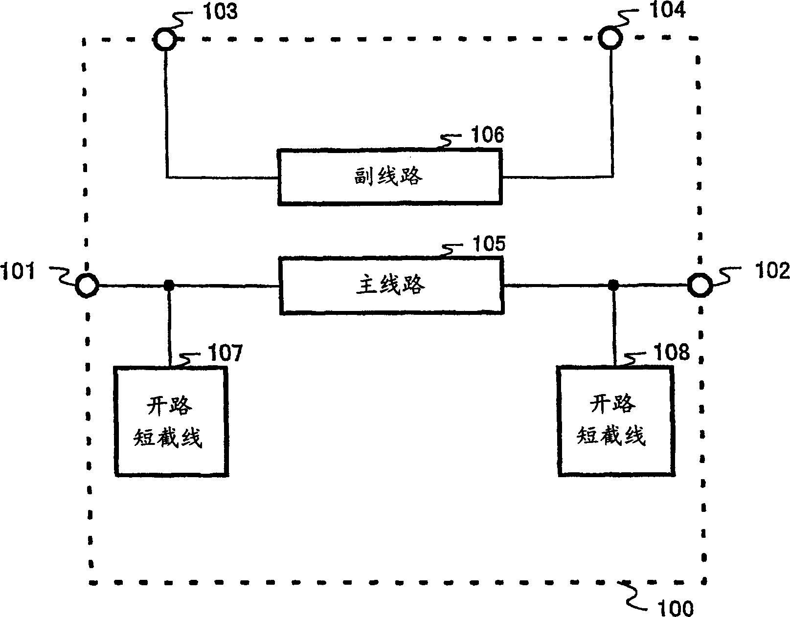
[0045] figure 1 It is a diagram showing a configuration example of a directional coupler according to Embodiment 1 of the present invention, and is a directional coupler applied to monitor transmission power.
[0046] The directional coupler 100 is mainly composed of an input terminal 101 , an output terminal 102 , a coupling terminal 103 , an isolation terminal 104 , a main line 105 , a secondary line 106 , an open stub 107 and an open stub 108 .
[0047] The input terminal 101 is connected to the output terminal 102 via an open stub 107 , a main line 105 , an open stub 108 . The coupling terminal 103 is connected to the isolation terminal 104 through the sub-line 106 electromagnetically coupled with the main line 105 .
[0048] The open stub 107 and the open stub 108 have the same characteristics, and have a stub length equivalent to 1 / 4 wavelength at the desired cutoff frequency fs11. The following describes making the characteristic impedance of the directional coupler c...
Embodiment 2
[0059] Below, use Figure 5 to Figure 8 Embodiment 2 of the present invention will be described. Figure 5 It is a diagram showing a configuration example of a directional coupler according to Embodiment 2 of the present invention, which is applied to a directional coupler for monitoring transmission power.
[0060] The directional coupler 500 is mainly composed of an input terminal 501 , an output terminal 502 , a coupling terminal 503 , an isolation terminal 504 , a main line 505 , a secondary line 506 , an open stub 507 and an open stub 508 . The input terminal 501 is connected to the output terminal 502 through an open stub 507 , a main line 505 , and an open stub 508 . The coupling terminal 503 is connected to the isolation terminal 504 through the sub-line 506 electromagnetically coupled with the main line 505 .
[0061] The open stub 507 and the open stub 508 have stub lengths corresponding to 1 / 4 wavelength at two different cutoff frequencies fs21 and fs22. The foll...
Embodiment 3
[0068] Below, use Figure 9 to Figure 12 Embodiment 3 of the present invention will be described. Figure 9 It is a diagram showing a configuration example of a directional coupler according to Embodiment 3 of the present invention, which is applied to a directional coupler for monitoring transmission power.
[0069] The directional coupler 900 is mainly composed of an input terminal 901 , an output terminal 902 , a coupling terminal 903 , an isolation terminal 904 , a main line 905 , a secondary line 906 , an open stub 907 , an open stub 908 and an open stub 909 . The input terminal 901 is connected to the output terminal 902 through an open stub 907 , a main line 905 , and an open stub 908 . An open stub 909 is arranged on the main line 905 . The coupling terminal 903 is connected to the isolation terminal 904 through the sub-line 906 electromagnetically coupled with the main line 905 .
[0070] The open stubs 907, 908 and 909 have stub lengths corresponding to 1 / 4 wavele...
PUM
| Property | Measurement | Unit |
|---|---|---|
| Thickness | aaaaa | aaaaa |
Abstract
Description
Claims
Application Information