Supersonic external-compression diffuser and method for designing same

A supersonic and diffuser technology, applied to supersonic aircraft, aircraft, mechanical equipment, etc., can solve the problems of large fairing resistance and large resistance

Inactive Publication Date: 2002-12-11
THE BOEING CO
View PDF0 Cites 33 Cited by
  • Summary
  • Abstract
  • Description
  • Claims
  • Application Information

AI Technical Summary

Problems solved by technology

However, externally pressurized inlets are generally not conducive to flight above about Mach 2.0 because they tend to have a lot of cowling drag as a consequence of having to achieve a lot of airflow diversion ahead of the inlet duct
this large amount of airflow turning results in large fairing angles and long fairing lengths across the direction of airflow, and thus high drag

Method used


Image

  • Supersonic external-compression diffuser and method for designing same
  • Supersonic external-compression diffuser and method for designing same
  • Supersonic external-compression diffuser and method for designing same

Examples


Embodiment Construction

[0027] The present invention will now be described more fully hereinafter with reference to the accompanying drawings, which show preferred embodiments of the invention. However, the invention may be embodied in many different forms and should not be construed as limited to the embodiments set forth herein; rather, these embodiments are provided so that this disclosure will be thorough, thorough, and fully convey the scope of the invention. communicated to those skilled in the art. Throughout, like reference numerals identify like elements.

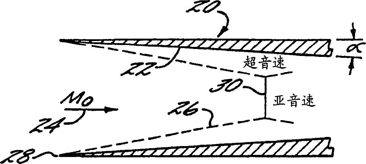
[0028] The invention is based on the principle that a supersonic pressurization field which substantially replicates the axisymmetric pressurization field of a closed duct axisymmetric diffuser can be produced by a duct which only partially surrounds the jet. This is accomplished by constructing a three-dimensional pressurized surface that fits the streamlines formed by the axisymmetric flow field. This three-dimensional pressurized sur...


PUM


Abstract

A supersonic externally pressurized inlet comprising a generally scoop-shaped supersonic pressurized portion for diffusing a supersonic free jet. The supersonic pressurization portion includes a main wall having a leading edge and a throat downstream of the leading edge; and sides joined to opposed side edges of the main wall to form a generally scoop-shaped member. The sides preferably protrude far enough into the supersonic flow to encompass the initial oblique shock attached to the leading edge of the main wall. The main wall has an inner surface generally formed as an inclined sector of the surface of revolution, the inner surface of the main wall cooperating with the inner surfaces of the sides to form a three-dimensional external pressurized surface. The supersonic external pressurization inlet also includes a subsonic diffuser section arranged to receive airflow from the supersonic pressurization section and diffuse the airflow to subsonic conditions. The variable geometry inlet includes an outer ramp hinged about its forward edge and forming part of the inner surface of the spoon diffuser, the pivotal movement of the outer ramp being used to vary the throat size of the inlet. The subsonic diffuser includes an inner ramp hinged around its trailing edge to maintain a smooth transition from the outer ramp.

Description

technical field [0001] This invention relates to supersonic diffusers. The invention more particularly relates to externally pressurized supersonic diffusers, such as those used as inlets in air-breathing propulsion systems. Background technique [0002] In many types of aircraft, air-breathing propulsion systems such as turbojet or turbofan engines are used to propel the aircraft at supersonic speeds. Gas turbine engines currently on the market for aircraft propulsion are virtually invariably designed to operate in a condition in which subsonic airflow, typically on the order of Mach 0.3 to 0.6, exists in the engine at the upstream end face. Thus, there is a need for a supersonic diffuser or intake to reduce the velocity of the trapped supersonic airflow to subsonic for intake by the engine. The deceleration process is known in the art as diffusion or pressurization, as the excess kinetic energy of the airflow is converted into a static pressure in...

Claims


Application Information

Patent Timeline
Patent Type & Authority Applications(China)
IPC IPC(8): B64C30/00B64D33/02F02C7/042F04D29/54F04D29/56
CPCB64C30/00B64D33/02B64D2033/026F02C7/042Y10T137/0536
Inventor 琳达·S·赫奇斯约瑟夫·L·康科塞克博比·W·桑德斯
Owner THE BOEING CO
Why Eureka
Try Eureka