Control valve of high-pressure pneumatic switch

A technology of pneumatic switch and control valve, applied in the direction of lift valve, valve details, valve device, etc., can solve the research and application limitations of high-pressure pneumatic switch valve, high sealing difficulty, low lubricity and other problems, and achieve reliable sealing design performance, Easy operation and small throttling loss

Inactive Publication Date: 2002-12-25
ZHEJIANG UNIV
View PDF0 Cites 35 Cited by
  • Summary
  • Abstract
  • Description
  • Claims
  • Application Information

AI Technical Summary

Problems solved by technology

However, due to the low viscosity and low lubricity of gas, the difficulty of sealing high-pressure gas is much higher than that of high-pressure liquid, and t

Method used


Image

  • Control valve of high-pressure pneumatic switch
  • Control valve of high-pressure pneumatic switch
  • Control valve of high-pressure pneumatic switch

Examples


Embodiment Construction

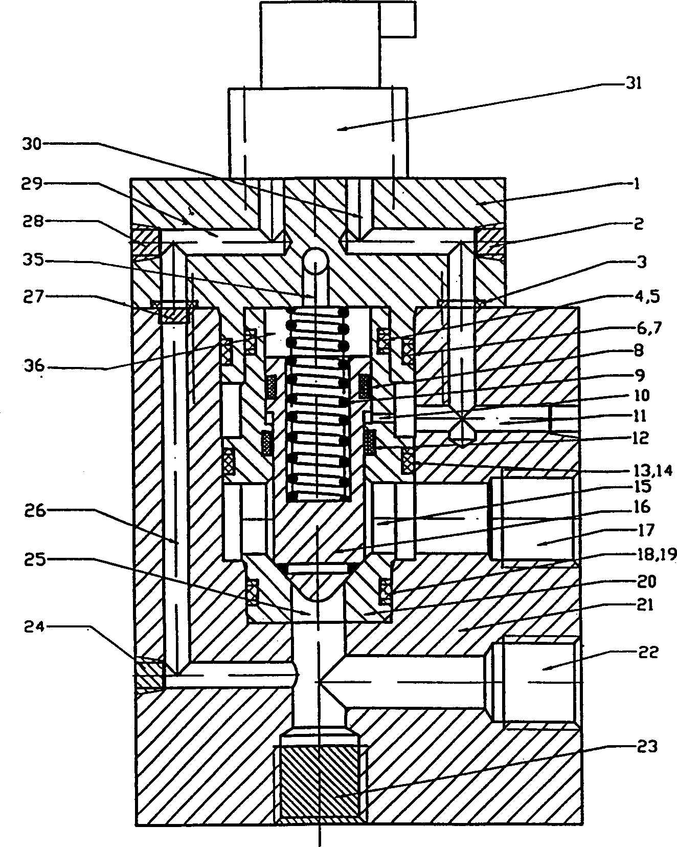
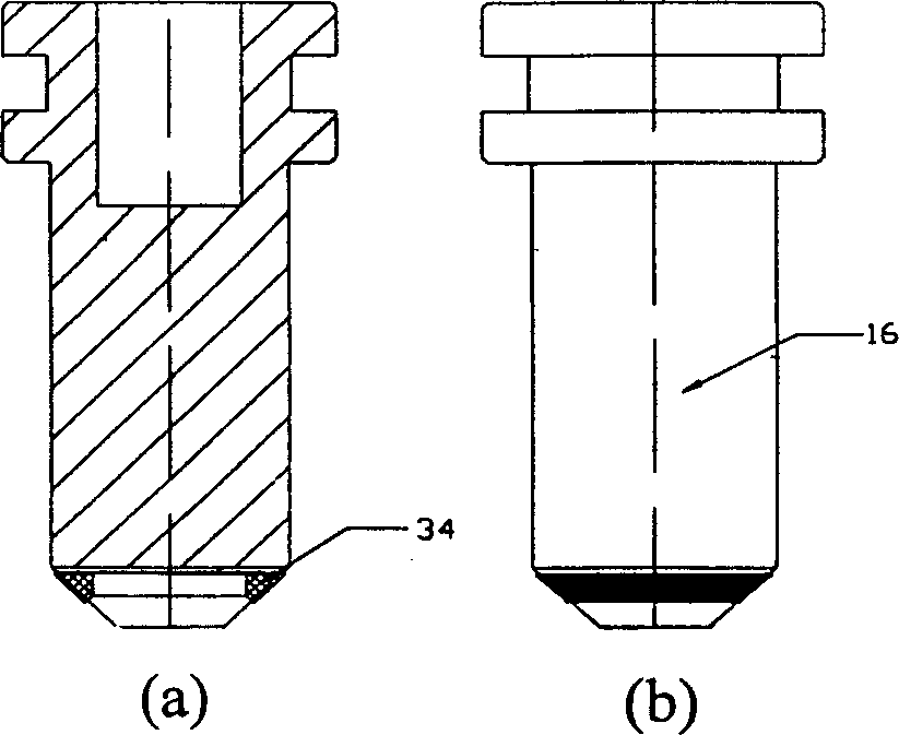
[0018] Such as figure 1 As shown, the high-pressure pneumatic switching valve is composed of an electromagnetic pilot valve part 31 and a main valve part. The pilot valve part is connected with the main valve part through an inner hexagon screw 33 . The pilot valve part adopts the electromagnetic ball valve with good sealing performance and high pressure resistance. The main valve part is composed of valve cover 1, cone valve core 16, valve sleeve 20, valve body 21 and other parts.

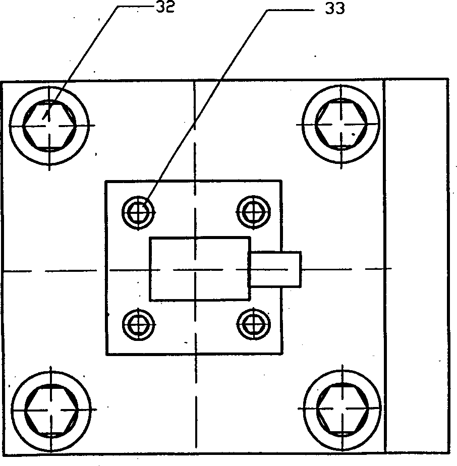
[0019] The bonnet part includes: such as figure 1 , figure 2 As shown, the plug 2 and the plug 28 installed on the bonnet 1, the seal ring 3 installed on the bonnet 1, the seal ring 6 and the retaining ring 7 installed on the bonnet 1, the control gas inlet channel 29 And control gas exhaust pressure relief passage 30. The valve cover 1 is installed in the valve body 21 and tightly connected by the hexagon socket head cap screw 32; the valve cover 1 and the valve body 21 are sealed by the se...


PUM


Abstract

A control valve of high-pressure pneuamtic valve is composed of main valve and magnetic pilot valve which is an electromagnetic high-pressure ball valve. Said main valve consists of valve cover, conic valve core, valve bush and main body. The sealing surface of conic valve core is made of vulcanized rubber. The PTFE is used for the seal between conic valve and valve bush. Its advantages are simple and compact structure, reliable sealing, and high flow controlled by electronic signals.

Description

technical field [0001] The invention relates to a high-pressure pneumatic switch control valve, which is a high-pressure pneumatic switch valve applied to volume expansion and decompression control of a high-pressure gas power system. Background technique [0002] In the field of background art, the closest thing to the present invention is a pneumatic on-off control valve of a conventional pneumatic system. Although the current technology is relatively mature, the existing pneumatic switch control valves at home and abroad can only be used in pneumatic systems with a system pressure lower than 3MPa, and are mostly used for small flow control. At present, there is no large-flow high-pressure pneumatic switch valve product higher than 3MPa. [0003] High-pressure gas is used as power, and the conventional decompression control method is to use a throttling pressure regulating device, which is reasonable for a pneumatic system that works intermittentl...

Claims


Application Information

Patent Timeline
IPC IPC(8): F16K1/00F16K31/06F16K31/122
Inventor 王宣银贾光政陈鹰陶国良许宏刘昊吴根茂
Owner ZHEJIANG UNIV
Why Eureka
Try Eureka