Apparatus for introducing sunlight to room

A technology of sunlight and daylighting devices, which is applied in the direction of solar thermal devices, lighting devices, heating devices, etc., can solve the problems of low utilization efficiency of light receivers, reduction of effective light receiving area, and reduction of light transmission efficiency, etc., to achieve daily maintenance work The effects of reducing energy consumption, improving energy utilization efficiency, and high social and economic benefits

Inactive Publication Date: 2002-12-25
谭洪源
View PDF1 Cites 39 Cited by
  • Summary
  • Abstract
  • Description
  • Claims
  • Application Information

AI Technical Summary

Problems solved by technology

The main defect of this device is: it is only applicable to the room directly on the floor below the roof of the building; since the reflector is directly used to reflect the light to the secondary reflector, there must be an angle between the direct sunlight and the reflector, which means The effective ligh

Method used


Image

  • Apparatus for introducing sunlight to room
  • Apparatus for introducing sunlight to room
  • Apparatus for introducing sunlight to room

Examples


Embodiment 1

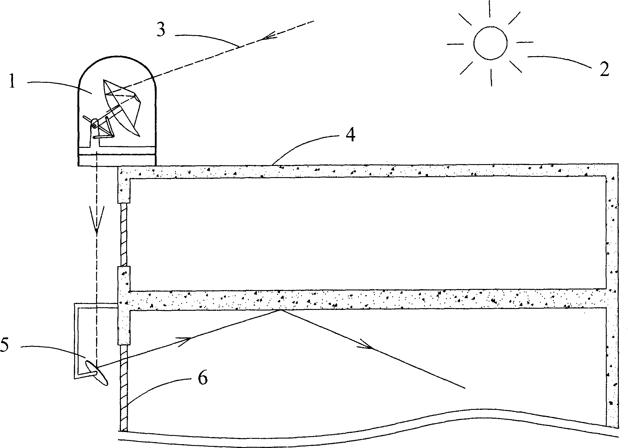
[0022] exist figure 1 Among them, the light collector 1 of the present embodiment is installed on the top of the building 4, and the direct light 3 of the sun 2 is converged by the light collector 1 to change the direction of propagation, and is always reflected to the surface of the front mirror 5 with a fixed path, and the front mirror 5 is a convex mirror, divergently reflects the transmitted light through the window 6 to the depth of the indoor room, so as to meet the indoor lighting requirements.

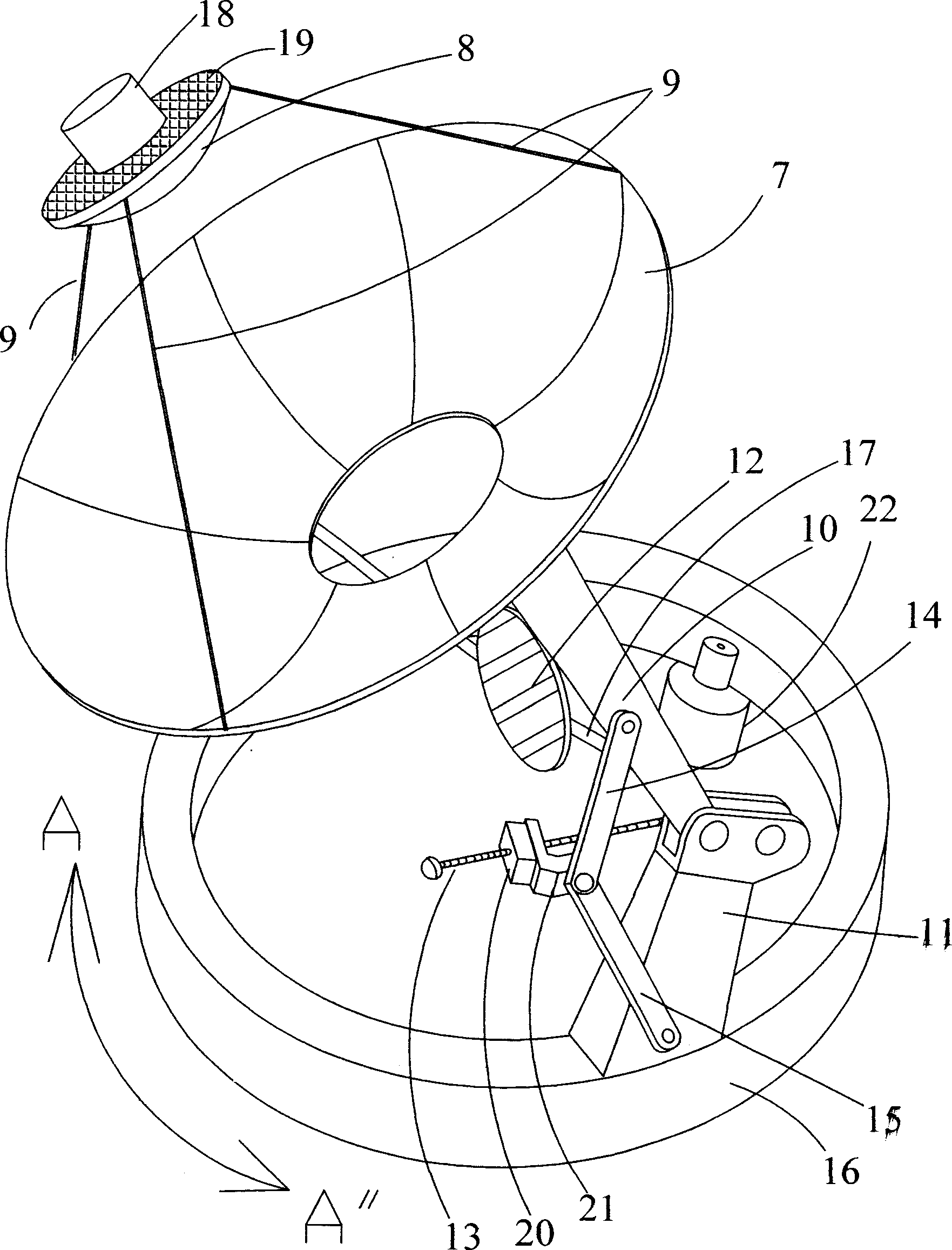
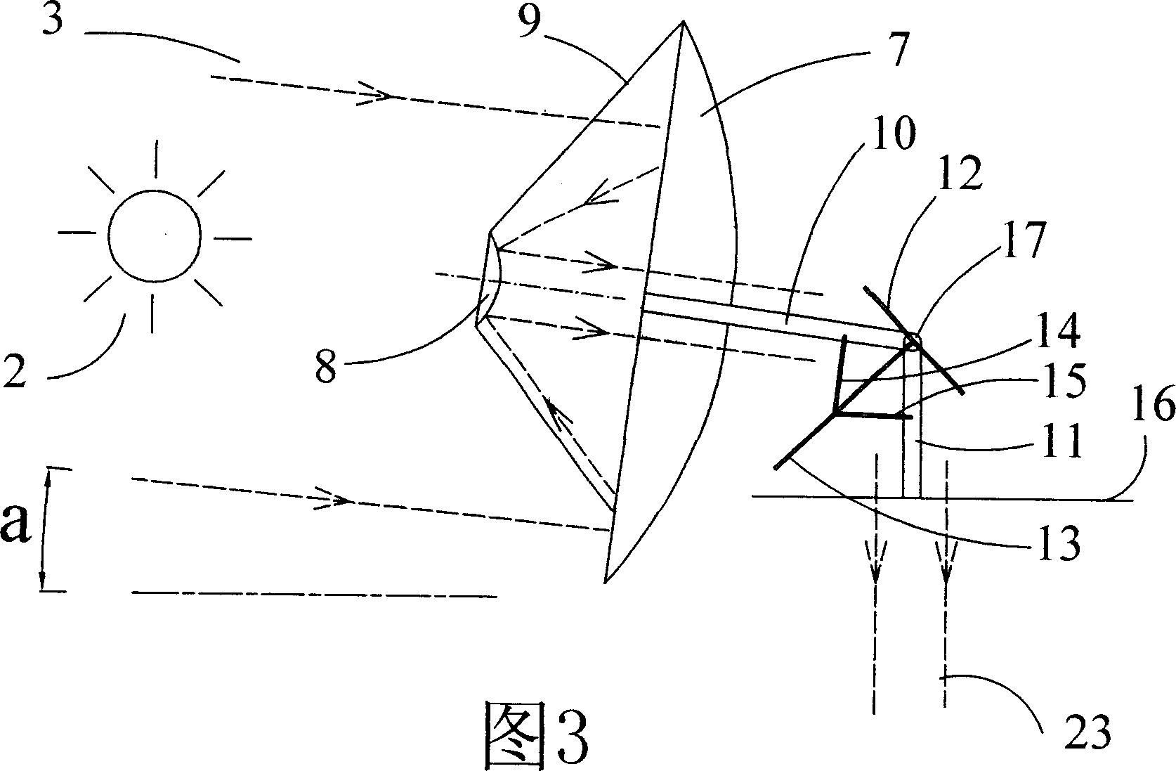
[0023] figure 2 -4 illustrates the structure and working principle of the light collector 1 of this embodiment. figure 2 Among them, the curved surface condenser 7 is hinged on the bracket 11 of the horizontal rotary table 16 through the bracket 10, and the horizontal rotary table 16 is driven by the horizontal actuator motor 22, and can rotate in both directions of A-A", so as to complete the tracking of the position of the sun in the horizontal direction of the device The...

Embodiment 2

[0027] The improvement of this embodiment on the basis of Embodiment 1 is: in Fig. 6, the optical receiving device adopts an optical lens 28, and the lens 28 converges the direct sunlight 3 on the surface of the direction control mirror 12, and after being reflected by the direction control mirror 12, it becomes a A beam of divergent light, the beam of light becomes parallel light 23 after being converged by the lens 29, the beam of parallel light is always irradiated to a fixed position and enters the room through the front mirror or optical fiber to diverge.

Embodiment 3

[0029] The improvement of this embodiment on the basis of Embodiment 1 is: Figure 7 In the above, after the light collector 1 transmits the light to a fixed location, the light is further converged by the optical coupler 26, coupled into the optical fiber 27, and then guided into the room through the optical fiber 27 and diverged for illumination. This embodiment makes full use of the advantages of high transmission efficiency, softness and easy wiring of optical fibers, and at the same time, because the transmission of long-distance light is carried out in the air, the usage of optical fibers is greatly reduced, which can save a lot of energy compared with the method of simply using optical fibers to transmit light. cost.


PUM


Abstract

A device for guiding sunlight into room is composed of light collector, mechanical assembly, cleaning arm, protecting cover, light-detecting sensor, control unit, and horizontal and tilting executingmotors. It can always collect sunlight and deliver it to needed position in room. Its advantages are high efficient and low cost.

Description

Technical field [0001] The invention relates to a device for transmitting sunlight into a room to improve indoor daytime lighting, especially a device capable of receiving sunlight with the largest light receiving area all the time and transmitting the sunlight into the room. Background technique [0002] With the acceleration of the urbanization process, the shading between buildings is becoming more and more serious, and due to the increasing depth of the building, the ability of the interior of the building to rely on sunlight during the day is getting weaker and weaker. Many buildings today, especially commercial buildings, often rely on artificial light sources for lighting during the day—even when the outside sun is shining. The sunlight entering the room can solve this contradiction, which uses optical devices to change the direction of sunlight propagation and guide it into the room for lighting. The use of this device can not only save a lot of energy, but also imp...

Claims


Application Information

Patent Timeline
IPC IPC(8): F21S11/00F21V8/00F21V9/00F21V13/04F24S50/20G02B17/00
CPCY02E10/47
Inventor 谭洪源
Owner 谭洪源
Why Eureka
Try Eureka