Device for making optical fiber powder-deposit and method for making powder-deposit using said device optical-fiber
A manufacturing device and technology for accumulating powder, which can be used in combustion methods, manufacturing tools, glass manufacturing equipment, etc., and can solve problems such as increased interference and deformation of core accumulated powder.
- Summary
- Abstract
- Description
- Claims
- Application Information
AI Technical Summary
Problems solved by technology
Method used
Image
Examples
Embodiment 1
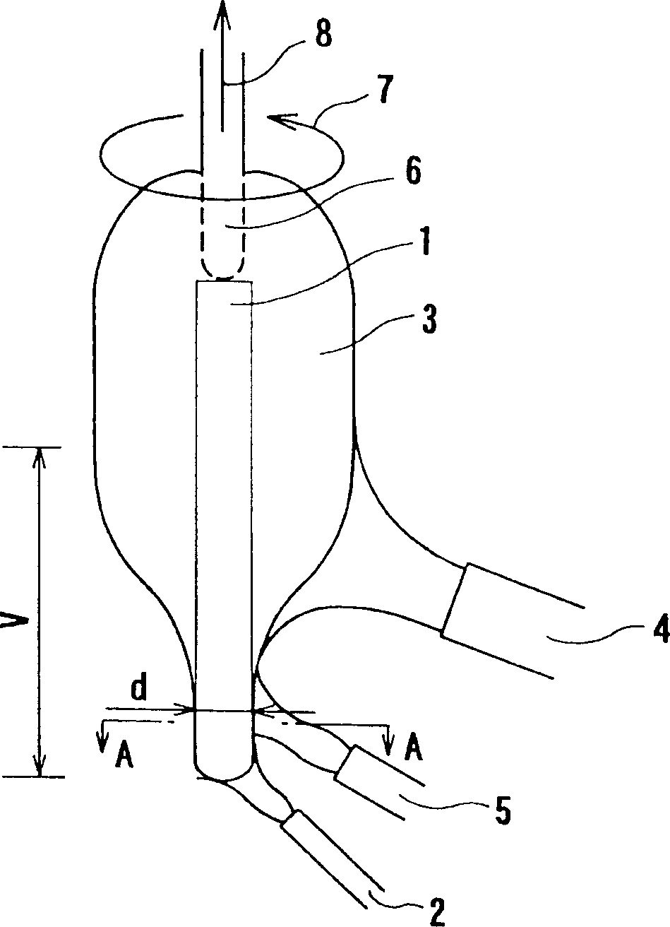
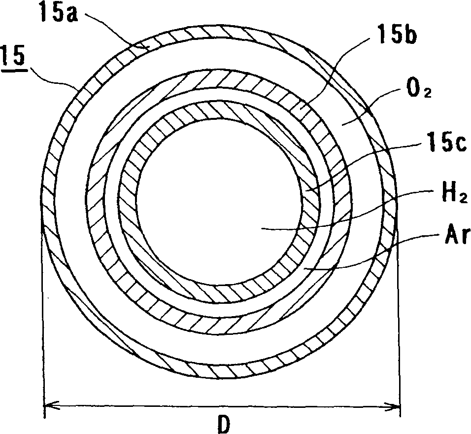
[0041] According to the VAD method, using figure 1 The core powder production test of the basic structure shown by figure 2 or image 3 The burners are used as side burners. exist figure 2 In the case of a conventional burner (where the burner outer diameter (width) D is 0.5d, where d is the diameter of the core portion), the cross-sections of nine of the 10 cores obtained by PA Measuring is not possible because of oversized slots. Furthermore, in the core whose profile could be measured, air bubbles appeared along the entire length of the obtained core.
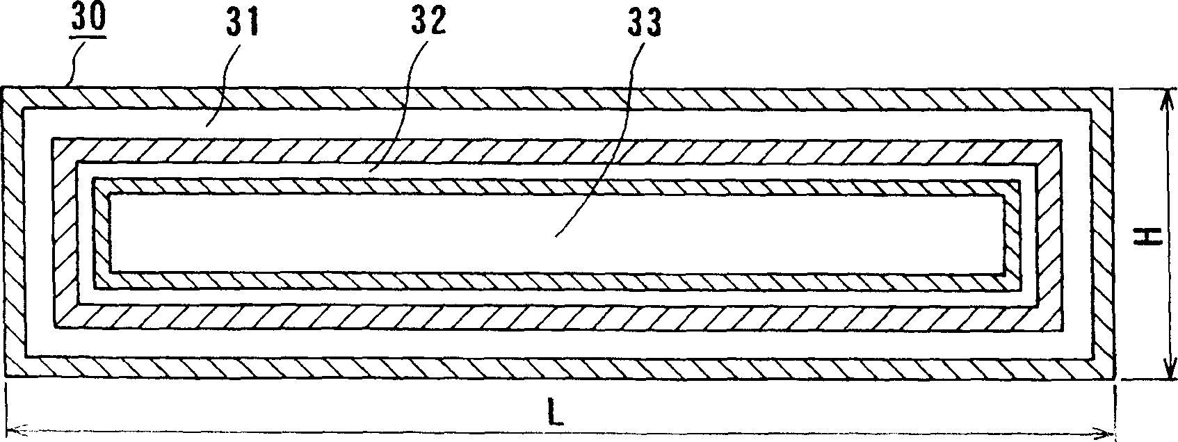
[0042] On the other hand, when using the image 3 In the case of the shown rectangular burner, when using a multi-tube burner with a width increased to 0.7d, no air bubbles were found and profile measurements could be performed. Example 2 :
Embodiment 2
[0043] Then, tests were carried out with respect to the length V of the tapered end portion, as figure 1 shown. defined by conventional burners (see figure 2 ) The length of the tapered end portion of the powder product produced is V 0 . when using figure 2 When the position of the cladding burner is moved upward, the length of the tapered end portion of the product becomes longer, 1.7V 0 . Therefore, positioning image 3 The rectangular side burner is such that the width with greater length is in the horizontal direction, and the width L of this burner is fixed at 0.7d. Synthesis was performed using a rectangular side burner by varying the height H of the burner according to two levels (eg 0.5d and 0.3d). As a result, the length of the tapered portion of the final product powder can be shortened, and V 0 and 0.7V 0 . The formation of air bubbles was not found, and the measurement of the profile could be performed. This relationship is Figure 4 shown in .
[00...
Embodiment 3
[0046] An embodiment using the burner cover of Fig. 8(a) and Fig. 8(b) is described below. Figure 9 is a graph illustrating the relationship between the height h of the shroud and the length V of the tapered portion of the end portion of the powder-cored body when the height h is varied while the height H of the burner is constant. from Figure 9 It is evident that the length V of the tapered portion of the end portion of the powder-cored body can be reduced by reducing the height of the outlet of the hood. This method is economical because the length (V) of the tapered portion of the end portion of the core powder body can be controlled by exchanging the burner cover. In addition, if the height h of the hood outlet is 0.5H or more with respect to the height H of the burner, the hood end portion can be used in a normal state without being burned.
PUM
 Abstract
Description
Claims
Application Information
 - R&D Engineer
- R&D Manager
- IP Professional
- Industry Leading Data Capabilities
- Powerful AI technology
- Patent DNA Extraction
Browse by: Latest US Patents, China's latest patents, Technical Efficacy Thesaurus, Application Domain, Technology Topic, Popular Technical Reports.
© 2024 PatSnap. All rights reserved.Legal|Privacy policy|Modern Slavery Act Transparency Statement|Sitemap|About US| Contact US: help@patsnap.com


