Supercharge Your Innovation With Domain-Expert AI Agents!

Planar CRT panel

A planar cathode and ray tube technology, applied in the direction of cathode ray tube/electron beam tube, cathode ray/electron beam tube shell/container, discharge tube, etc., can solve problems such as cracking, thick flat panel, and high cost

Inactive Publication Date: 2003-02-26
LG PHILIPS DISPLAY KOREA CO LTD
View PDF0 Cites 1 Cited by
  • Summary
  • Abstract
  • Description
  • Claims
  • Application Information

AI Technical Summary

Problems solved by technology

That is to say, the overall thickness of the planar panel 1 is larger than that of the non-planar panel 1a, which will cause the panel to generate a high stress value exceeding the critical stress value due to the difference in heat conduction during heat treatment, thereby causing cracking
That is, in essence, cracking limits the structure of the planar panel 1
[0011] Secondly, the plane panel 1 is relatively thick, heavy, and costly, requiring components such as frames to be relatively large

Method used


Image

  • Planar CRT panel
  • Planar CRT panel
  • Planar CRT panel

Examples


Embodiment Construction

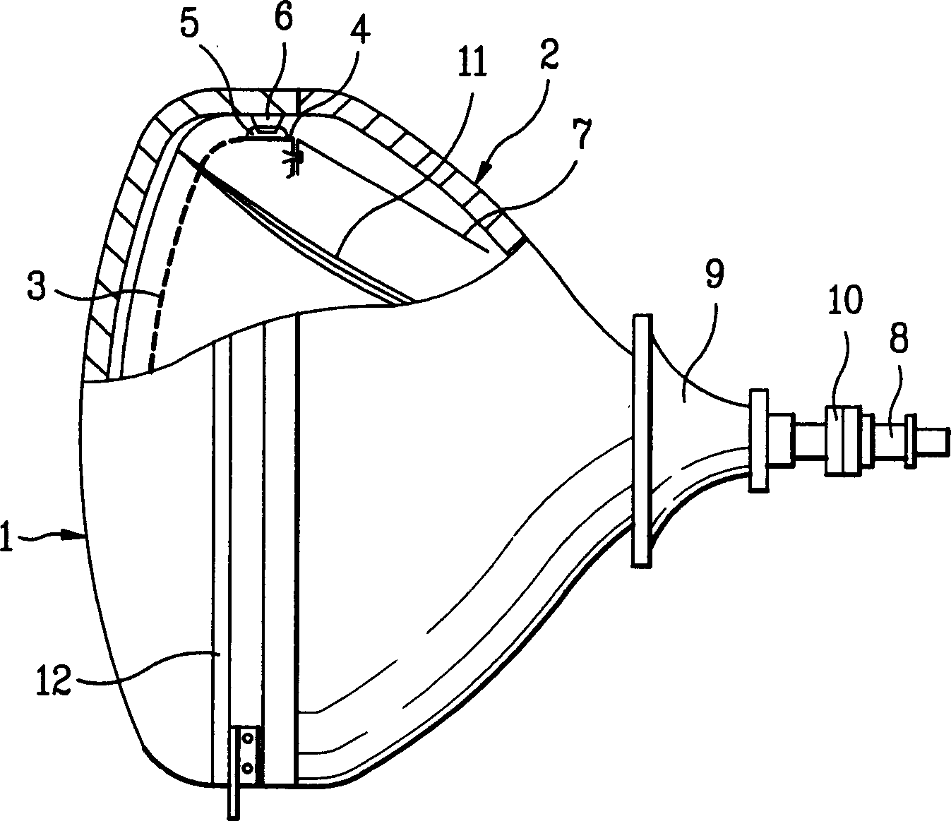
[0034] Reference will now be made in detail to the preferred embodiments of the invention, examples of which are illustrated in the accompanying drawings.

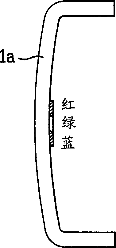
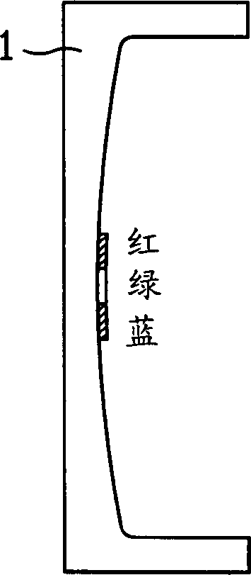
[0035] The wedge of the planar panel in Figure 2B, ie the ratio of the outer thickness to the center thickness of the panel, is greater than that of the non-planar panel shown in Figure 2A. Especially large CRTs over 29" with a wedge greater than 200% have a higher rate of cracking during heat treatment.

[0036] In order to solve this problem, it may be considered to design only the curvature radius of the inner surface of the panel to be larger. However, although this method reduces the wedge, there is a problem that the surface strength of the shadow mask having a curvature similar to that of the inner surface of the panel becomes weaker. Therefore, it is required to find an optimal panel curvature that can reduce the furnace thermal crack rate without reducing the strength of the shadow mask.

[0037] see Figure 4 ...


PUM

PropertyMeasurementUnit
Thicknessaaaaaaaaaa
Thicknessaaaaaaaaaa

Abstract

Flat CRT panel including a substantially flat outside surface, and an inside surface of a fixed curvature, wherein the inside surface of the panel is formed to meet a condition of {(Rh+Rv)2}xRd =8.0 - 10.3, where 'Rd' denotes a representative diagonal sectional radius of curvature, 'Rh' denotes a representative long-axis sectional radius of curvature, and 'Rv' represents a representative short-axis sectional radius of curvature when an effective screen size of the panel is greater than 25, thereby reducing thermal breakage, and permitting fabrication of lighter panel.

Description

[0001] This application claims priority from Korean Patent Application No. P2001-44557 filed on Jul. 24, 2001, which is hereby incorporated by reference. technical field [0002] The present invention relates to a flat cathode ray tube (CRT), and more particularly, to a flat cathode ray tube panel capable of reducing weight and cracking during heat treatment. Background technique [0003] The structure of a color cathode ray tube in the related art will be explained below with reference to FIG. 1 . [0004] A funnel 2 is installed behind the panel 1 . The inner surface of the panel 1 is coated with a fluorescent film, and the electron gun 8 packaged inside the funnel 2 is used to emit electron beams 11 to make the fluorescent film on the panel 1 emit light. A deflection coil 9 and a magnetic field 10 are used to deflect the electron beam 11 to the desired path. The bolt 6 inside the panel 1 is used to fix the main frame 5, on which the spring 4 of the shadow mask 3 and the...

Claims


Application Information

Patent Timeline
IPC IPC(8): H01J29/02H01J29/86
CPCH01J29/861H01J2229/862H01J29/02
Inventor 都基薰丁圣翰
Owner LG PHILIPS DISPLAY KOREA CO LTD
Features
  • R&D
  • Intellectual Property
  • Life Sciences
  • Materials
  • Tech Scout
  • Unparalleled Data Quality
  • Higher Quality Content
  • 60% Fewer Hallucinations
Learn More