Air filter and air conditioning device
An air filter and air-conditioning device technology, which is applied in air-conditioning systems, dispersed particle filtration, space heating and ventilation, etc., can solve the problems of increasing manufacturing costs, reducing the installation operability of the upper suction grille, and difficult operation, etc., to achieve The effect of improving performance
- Summary
- Abstract
- Description
- Claims
- Application Information
AI Technical Summary
Problems solved by technology
Method used
Image

Examples
no. 1 example
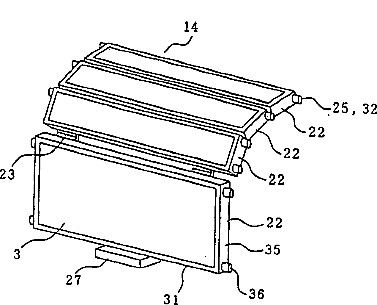
[0039] The following will refer to figure 1 , Fig. 2 explains the first embodiment of the present invention.
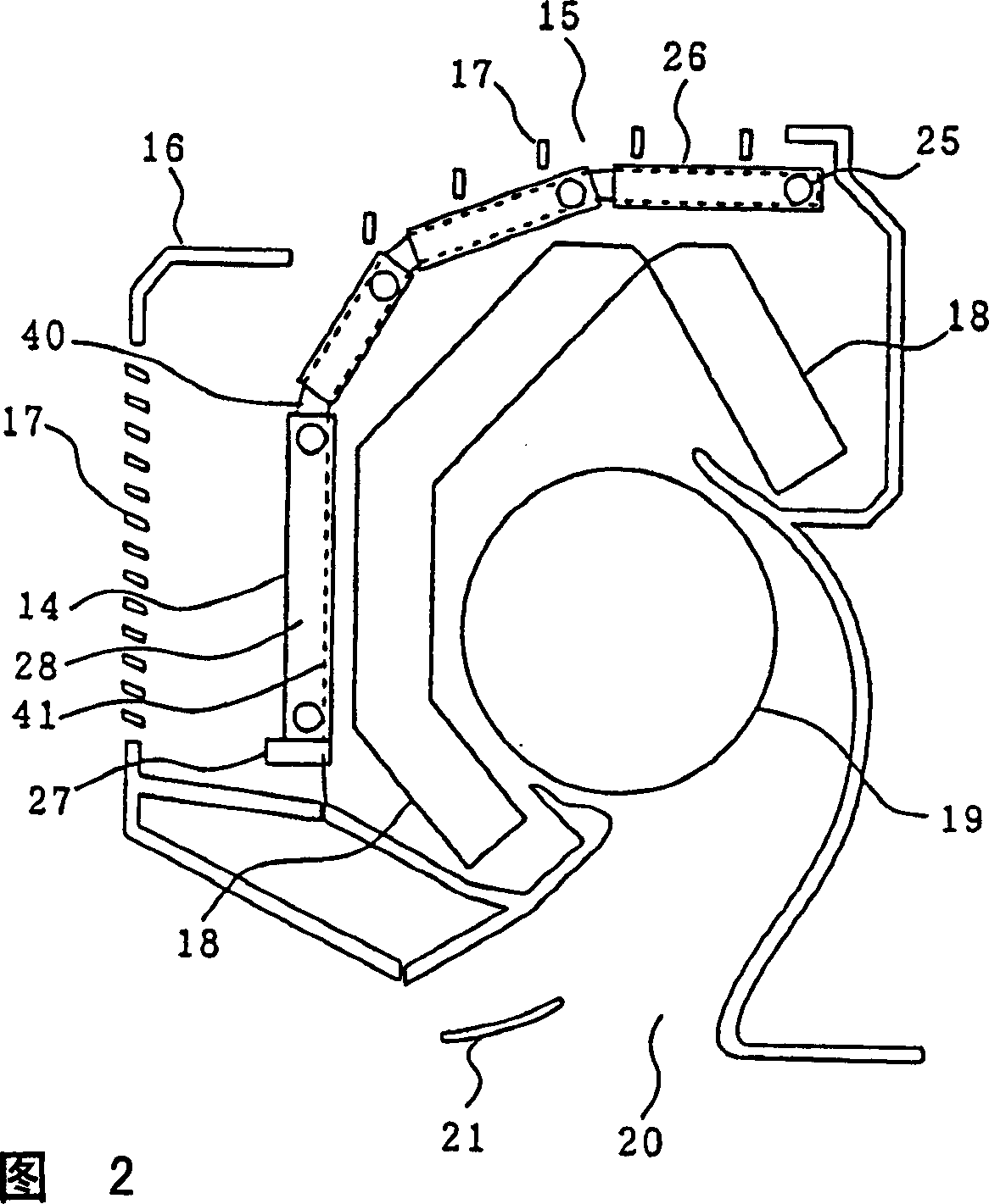
[0040] figure 1 is a perspective view of the air filter of the first embodiment. Fig. 2 is a cross-sectional view of an air conditioner (or air conditioner and refrigeration device) equipped with an air filter.
[0041] exist figure 1 -Among Fig. 2, the front portion of the panel 16 that is arranged on the air conditioner 15 of the room is provided with the grille 17 of air inlet, and the rear of this air inlet grille 17 is built-in blower 19 and covers this blower 19 ground configuration heat exchanger 18. The lower part of the panel 16 is provided with an air outlet 20 , and the switch and blowing direction of the air outlet 20 can be adjusted by using the damper 21 .
[0042] Between the grill 17 and the heat exchanger 18, the air filter 14 is attached so that the cross section of the heat exchanger 18 may fit. A plurality of hinges 23 are used to connect ...
no. 2 example
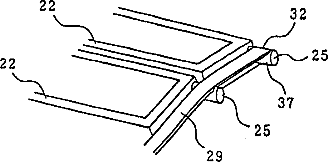
[0060] In the first embodiment, at least one boss portion 25 protrudes from both sides 35 of the unit filter frame member 22, and the boss portion 25 is inserted into the curved fitting groove 26 of the panel 16 and connected to each other when installed. The unit filter frame member 22, and in this embodiment, such as image 3 As shown, between the bosses 25 on both side surfaces 35 of the unit filter frame member 22, the bosses 25 on the same side 35 are connected to a deformable flat guide belt 29 as an elastic body. The guide portion 32 composed of the boss portion 25 and the guide band 29 connected to the boss portion is inserted into the curved fitting groove 26 of the panel 16, and the unit filter frame members 22 connected to each other are mounted thereon.
[0061] The guide band 29 is formed along the side surface 37 of each boss portion 25 of the unit filter frame member 22 , and is connected to the front side or the rear side of the side surface 37 of the adjacent ...
no. 3 example
[0068] In the first and second embodiments, the size of the section 36 of the boss portion 25 protruding outward on the side surface 35 of the unit filter frame part 22 is the same, but as Figure 4 As shown, in this embodiment, the size of the section 36 of the boss portion 25 is closer to the installation port 40 of the fitting groove 26 like the boss portions 25a, 25b, 25, 25d (the guide portion of the air filter The larger the size of the insertion port side), the whole guide portion 32 forms a wedge shape. In addition, the fitting groove 26 also cooperates with the guide portion 32 to form a wedge shape. Therefore, during assembly, the boss portion 25 and the fitting groove 26 can be Fitting without gaps ensures that the air filter 14 remains on the panel 16, thereby preventing the running air conditioner 15 from making cracking noises when vibrating and providing a good quality air conditioner 15.
[0069] In the actual assembly process, such as Figure 4 As shown, the ...
PUM
 Abstract
Description
Claims
Application Information
 - R&D
- Intellectual Property
- Life Sciences
- Materials
- Tech Scout
- Unparalleled Data Quality
- Higher Quality Content
- 60% Fewer Hallucinations
Browse by: Latest US Patents, China's latest patents, Technical Efficacy Thesaurus, Application Domain, Technology Topic, Popular Technical Reports.
© 2025 PatSnap. All rights reserved.Legal|Privacy policy|Modern Slavery Act Transparency Statement|Sitemap|About US| Contact US: help@patsnap.com