Ink jet for piezoelectric ink jetting head and its making process

The technology of an inkjet device and manufacturing method, which is applied in printing and other directions, can solve the problems of reducing ink efficiency, ink disturbance, and limitation, and achieve the effects of avoiding inaccurate pressing alignment, shortening process time, and short process time

Inactive Publication Date: 2003-03-19
NANODYNAMICS INC
View PDF1 Cites 6 Cited by
  • Summary
  • Abstract
  • Description
  • Claims
  • Application Information

AI Technical Summary

Problems solved by technology

(2) The piezoelectric material has a fast response speed, which can increase the printing speed; the thermal foam type is limited by the heating and cooling speed, so the printing speed of the nozzle is limited
(3) The piezoelectric inkjet head can control the droplet size by controlling the vibration of the piezoelectric vibrating plate to improve the printing quality; the thermal bubble type can only control whether the spray point is sprayed or not, and it is difficult to control the ink droplet size
This inward pulling force will

Method used


Image

  • Ink jet for piezoelectric ink jetting head and its making process
  • Ink jet for piezoelectric ink jetting head and its making process
  • Ink jet for piezoelectric ink jetting head and its making process

Examples


Example Embodiment

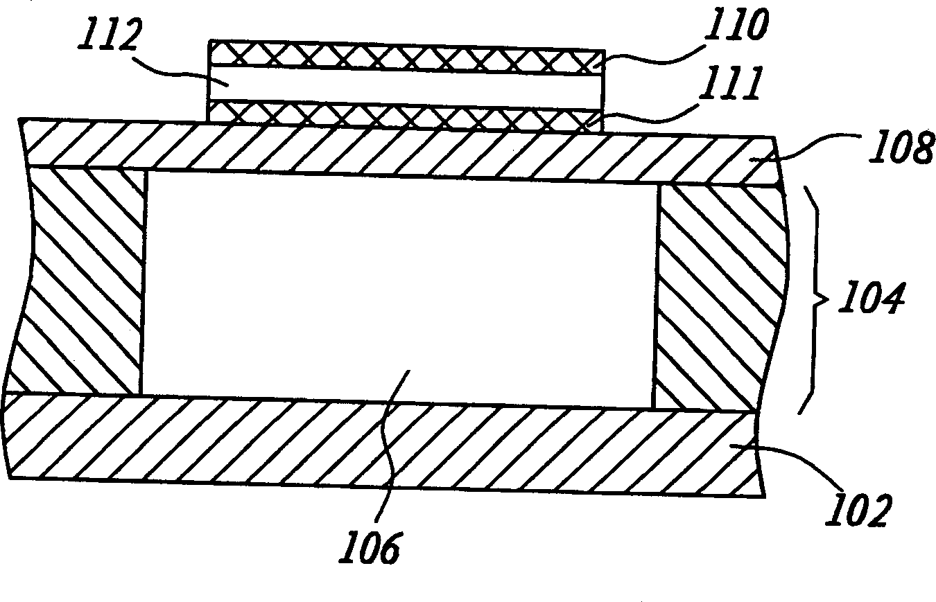
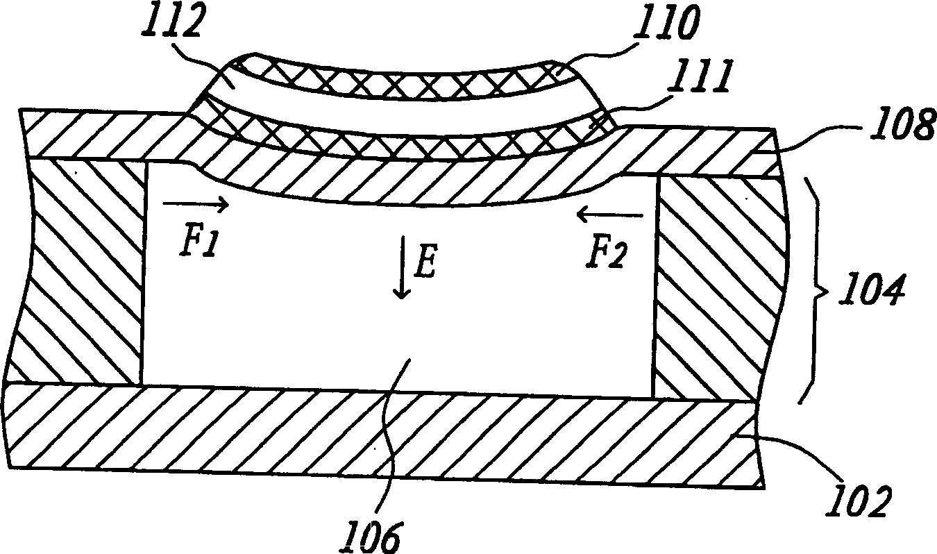
[0024] The technical feature of the present invention is that an ink cavity is defined on a substrate, and a metal sheet is used as the vibration layer of the piezoelectric inkjet head. The material of the base material may be a silicon wafer, a ceramic substrate, or a metal sheet. The metal sheet is formed on the substrate by electroforming, physical vapor deposition (Physical Vapor Deposition, PVD), or chemical vapor deposition (Chemical Vapor Deposition, CVD) to form a metal vibration layer.

[0025] In this preferred embodiment, a silicon wafer is used as the base material to illustrate the manufacturing process of the piezoelectric inkjet head of the present invention, but the present invention is not limited thereby.
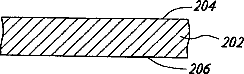
[0026] Please refer to Figures 2A-2F , which represents a part of the manufacturing process of the ink jet device of the piezoelectric ink jet head according to a preferred embodiment of the present invention. First, a silicon wafer 202 is provided as a...


PUM


Abstract

THe ink jet includes ink cavity, lower driving electrode, piezoelectric element and upper driving electrode, and its ink cavity includes vibrating metal layer and jet hole sheet. The making process includes the steps of: providing one substrate with top side and bottom side; forming one vibrating metal layer on the top; forming several ink cavities to expose partial vibrating metal layer and forming piezoelectric vibrating element with upper and lower electrodes one the vibrating metal layer. The substrate for etching may be silicon chip, ceramic sheet or metal sheet. The vibrating metal layer is formed with Ni, Cu, Pt or other metal via electric casting process, physical vapor deposition process or chemical vapor deposition process.

Description

technical field [0001] The present invention relates to an inkjet device of a piezoelectric inkjet head and a manufacturing method thereof, and in particular to a piezoelectric inkjet head that can be formed by etching a silicon wafer, ceramics, or metal as a substrate (Substrate) An inkjet device with an ink chamber and a manufacturing method thereof. Background technique [0002] In recent years, driven by the high-tech industry, all electronics-related industries have flourished. Take printers as an example. In just a few years, printing technology has progressed from strike pin type and black and white laser to color inkjet and color laser. It can be described as a rapid progress. Most of the inkjet printers currently on the market use thermal bubble or piezoelectric inkjet heads to spread ink onto paper to complete printing. The bubble type uses a heater to vaporize the ink instantly, and generates high-pressure bubbles to push the ink out of the nozzle. The piezoele...

Claims


Application Information

Patent Timeline
IPC IPC(8): B41J2/14B41J2/16
Inventor 杨长谋林振华李世光张所鋐
Owner NANODYNAMICS INC
Why Eureka
Try Eureka