Mechanical seal device

A technology of mechanical sealing device and sealing ring, which is applied in the direction of engine sealing, mechanical equipment, engine components, etc., can solve the problems of poor fluidity of sealing fluid, complex overall structure, thermal deformation of sealing surface, etc., and achieve the goal of improving the sealing effect Effect

Inactive Publication Date: 2003-04-09
EAGLE INDS
View PDF1 Cites 32 Cited by
  • Summary
  • Abstract
  • Description
  • Claims
  • Application Information

AI Technical Summary

Problems solved by technology

However, due to the structural limitations of the device, it is often not possible to enlarge the diameter of the inner peripheral surface of the stuffing box 150.
Therefore, the gap between the inner peripheral surface 156 of the stuffing box 150 and the liquid sealing device 101 becomes smaller, causing the fluidity of the sealing fluid to deteriorate, and the sliding friction between the rotating sealing surface 103 and the fixed sealing surface 113 cannot be cooled. damage to the sealing surface
[0012] Moreover, even if liquid is injected from the flush port 158, it is difficult to clean the liquid sealing device 101.
[0013] Especially, in the case of the fluid to be sealed containing slurry or the fluid to be sealed with high viscosity, between the liquid sealing device 101 and the inner peripheral surface 156 of the stuffing box 150, it is easy to be clogged by the slurry contained in the sealing fluid, thereby causing sliding. When the cooling effect of the sealing surfaces 103, 113 is deteriorated, the sealing ability of the two sealing surfaces 103, 113 is reduced at the same time, which in turn causes the sealed fluid to leak from between the sealing surfaces 103, 113
[0014] There is also the problem that the spring 105 is in direct contact with the sealed fluid, causing the spring 105 to corrode, rust, and reduce its elasticity, or the mud of the sealed fluid is attached to the spring 105, causing the spring 105 to elastically push the rotating seal ring 102. Furthermore, sludge will adhere to and enter the sliding surface between the rotating seal ring 102 and the sleeve 153, or the sliding surface between the liner 108 and the sleeve 153, resulting in a decrease in the surface pressure of the rotating sealing ring 102. Responsiveness deteriorates, reducing sealing ability
[0015] In this way, the liquid sealing device 101 must be provided with a double sealing device due to the reduced sealing ability, the overall structure becomes complicated, and the necessary assembly accuracy must be achieved.
In particular, the complicated structure of the liquid sealing device 101 makes it difficult to cool the rotating seal ring 102 and the stationary seal ring 113, which may cause thermal deformation of the sealing surfaces 103, 113, reduce the sealing performance, and cause damage to the sealing surfaces.

Method used


Image

  • Mechanical seal device
  • Mechanical seal device
  • Mechanical seal device

Examples


Embodiment Construction

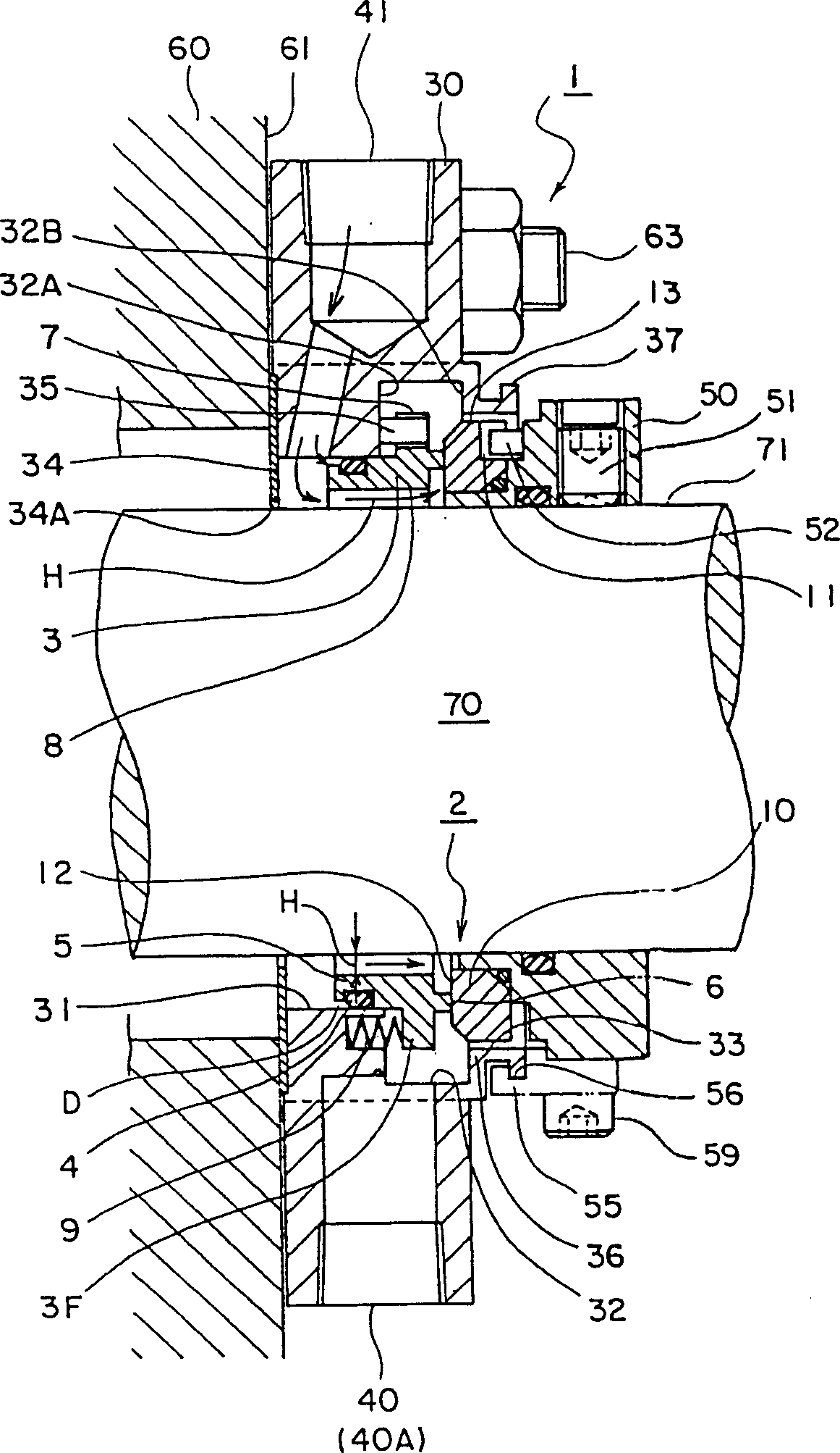
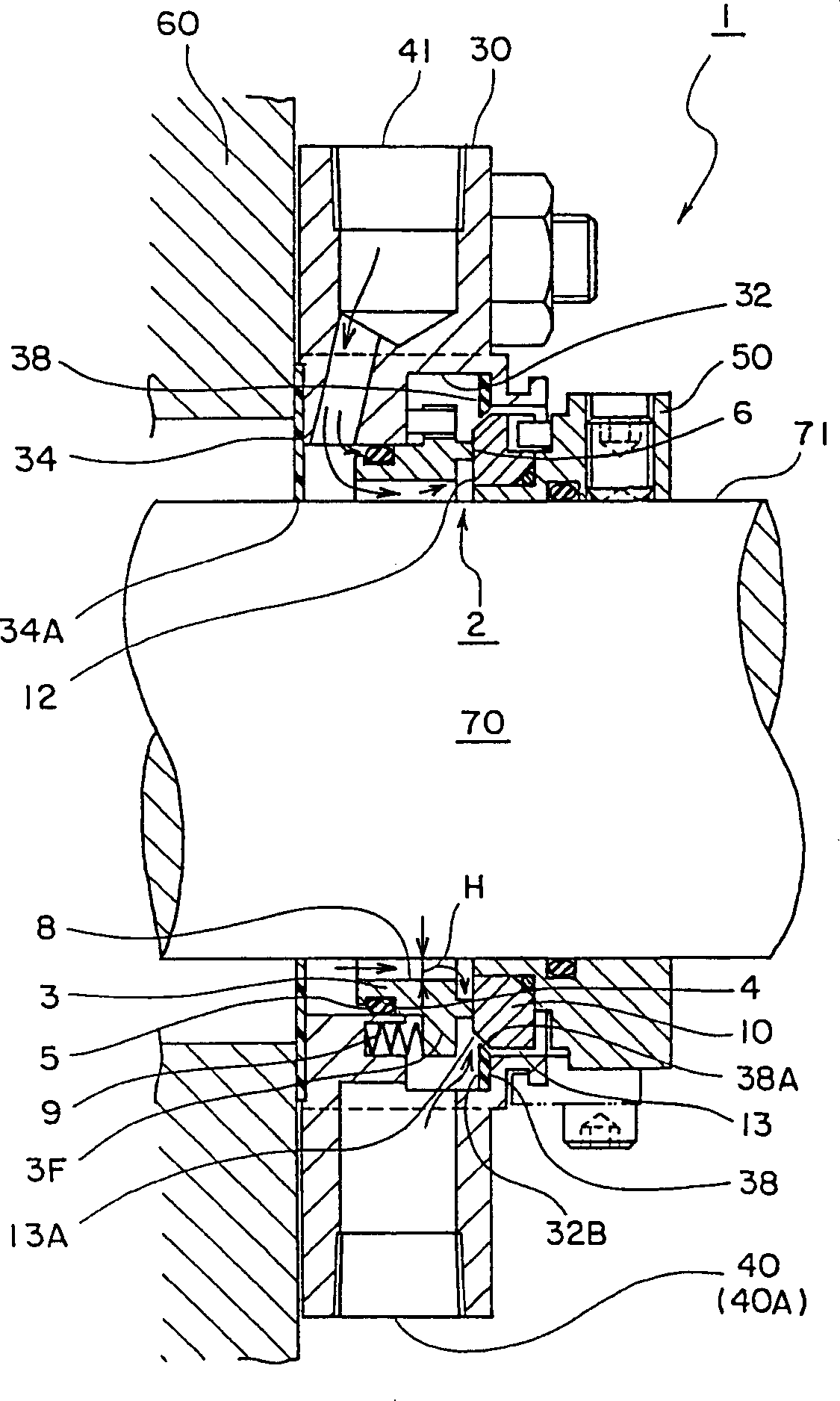
[0039] Hereinafter, the mechanical seal device 1 according to the embodiment of the present invention will be described in detail with reference to the accompanying drawings. In addition, the following drawings are not conceptual drawings for patent use, but are design drawings with accurate dimensional relationships based on experimental data.

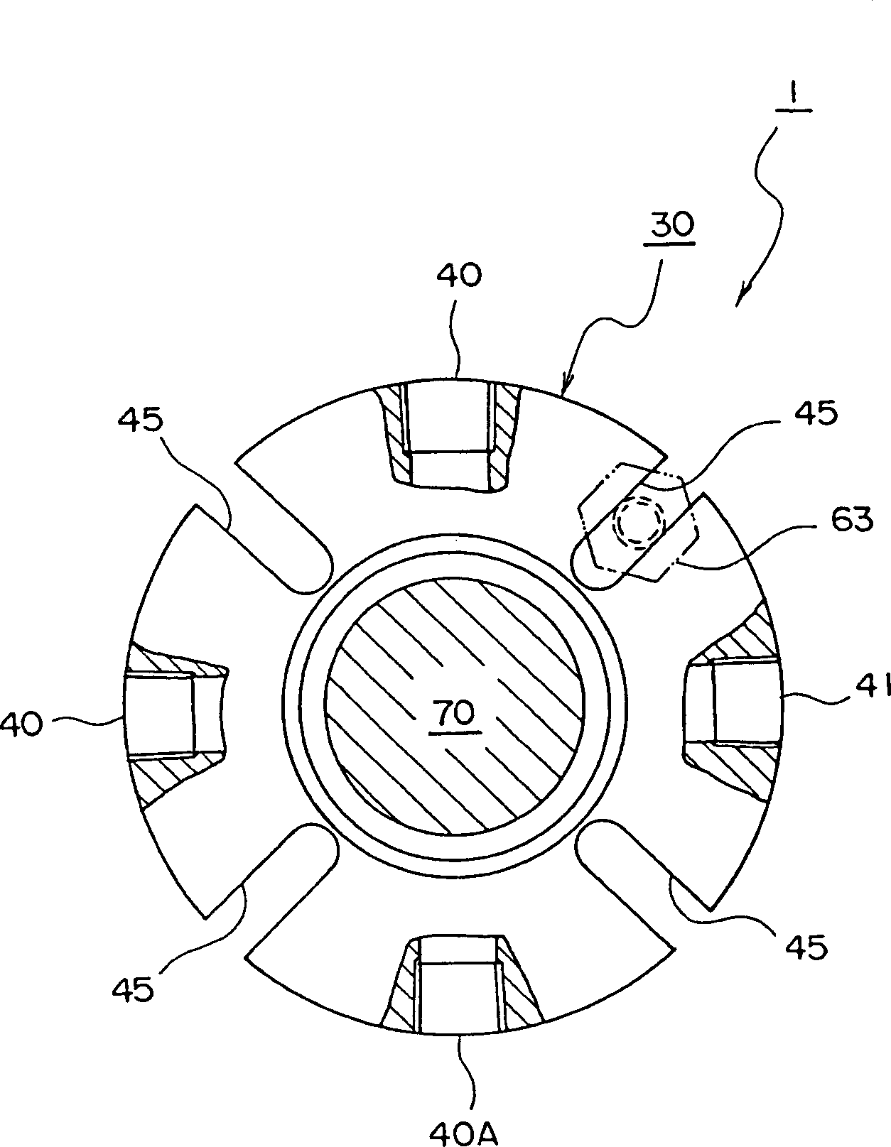
[0040] figure 1 This is a cross-sectional view of the mechanical seal device 1 of the present invention as a clip fitted to the outside of the device main body (stuffing box) 60 and the rotating shaft 70 . figure 2 Yes figure 1 The axial plan view of the mechanical seal device 1 after being fitted on the rotating shaft 70 .

[0041] figure 1 The mechanical seal device 1 according to the first embodiment of the present invention is shown. Should figure 1 The mechanical sealing device 1 is installed after positioning the sealing flange 30 mounted on the outer surface 61 of the device main body 60 and the sealing collar 50 embe...


PUM


Abstract

A first seal ring (3) has a clearance H allowing the passage of a sealed fluid, between a shaft (70) and the first seal ring (3) and constituted to communicate a flushing port (41) with the inner peripheral side of the seal face (6) through the clearance (H). A mounting part (30) has a cooling annular groove (32) in the form of covering the seal face (6) of the first seal ring (3) mounted to the inner peripheral surface (8), from the outer diameter side, and the outer throttle face (33) of the cooling annular groove (32) is fitted in proximity to the outer peripheral seal face of a second seal ring (10) while having a cooling fluid passage (40) communicating with the cooling annular groove (32). The invention reduce the sliding heat of a seal face while preventing clogging and sticking of solid matter of a sealed fluid to a mechanical seal externally mounted to a device body.

Description

technical field [0001] The present invention relates to a mechanical seal device, in particular to a ferrule-type mechanical seal device suitable for sealing a sealed fluid containing a high viscosity sealed fluid or slurry without adhesion or clogging between constituent parts by solids of the sealed fluid. Background technique [0002] The technology prior to the present invention is that described in the detailed specification of US Patent No. 4,290,611. Figure 5 is the appendix of this U.S. Patent No. 4,290,611 Figure 4 A half cross-sectional view of a generally marketed mechanical seal arrangement shown and associated with this patent. [0003] Figure 5 Among them, 100 is a mechanical seal device, the mechanical seal device 100 is mounted on the rotating shaft 151, and is mounted in the stuffing box 150 by bolts 160, and a pair is formed for this purpose. [0004] The main components of the mechanical seal device 100 are the liquid seal device 101 , the first seal f...

Claims


Application Information

Patent Timeline
Patent Type & Authority Applications(China)
IPC IPC(8): F16J15/06F16J15/34
CPCF16J15/3404F16J15/348
Inventor 高桥秀和
Owner EAGLE INDS
Why Eureka
Try Eureka