
Lens tester

A measuring instrument and lens technology, which is applied in the field of lens measuring instruments and can solve problems such as conjugate relationship offset

Inactive Publication Date: 2003-04-16
KK TOPCON
View PDF2 Cites 16 Cited by
  • Summary
  • Abstract
  • Description
  • Claims
  • Application Information

AI Technical Summary

Problems solved by technology

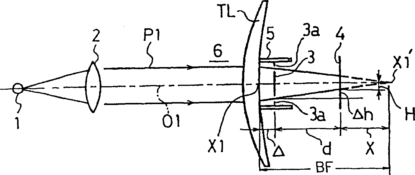
[0018] The difference is that if a test lens TL with positive magnification is placed in the measurement optical path 17, the parallel light beam P2 that passes through the test lens TL after being incident from the concave side of the test lens TL, due to the test lens TL The TL effect produces refraction in the direction of convergence, and the conjugate relationship between the target plate 12 and the area sensor 15 shifts

Method used


Image

  • Lens tester
  • Lens tester
  • Lens tester

Examples


Embodiment 2

[0092] Figure 15 Shown is an optical system of a lens measuring instrument of the type in which a measurement beam enters the lens under test TL from the concave side of the lens under test TL and emits a parallel beam P2 from the convex side of the lens under test TL. in the Figure 15 in, for with Figure 5 The same constituent elements are assigned the same symbols and will be described below.

[0093] On the target board 12 as Figure 16 As shown, five openings 12a-12e are formed. The opening 12a is located on the measurement optical axis O1, and four openings 12b-12e are formed at equal intervals around the opening 12a. In addition, 15 ′ is an area sensor 15 .

[0094] It is assumed that each of the LEDs 10 a - 10 d is made to emit light, and the measurement beam is led to the target plate 12 by the collimator lens 11 . In addition, the eccentric position X3 of the measured lens TL is located on the measurement optical axis O1.

[0095] The target board 12 is loca...

Embodiment 3

[0103] Figure 18 Shown is the optical system diagram of the lens measuring instrument using the shadow measurement method. The collimator lens 2 is used to make the parallel light beam enter the lens TL under test. When the lens TL under test is not placed in the measurement optical path 6, the focus lens 40 is used to The light source images of LED1a and 1b are formed at eccentric positions deviated from the rotation axis O3 of the rotation pattern plate 41, and a predetermined opening pattern is formed on the rotation pattern plate 41, and the rotation pattern plate 41 rotates at a certain period around the rotation axis O3.

[0104] When the tested lens TL is a convex lens, the focused light source images of LED1a and 1b are formed in front of the rotating graphic board 41, and when the tested lens TL is a concave lens, the focused light source images of LED1a and 1b are formed behind the rotating graphic board 41 picture. An imaging lens 42 is arranged between the rotati...


PUM


Abstract

The prensent invention provides a lens meter capable of eliminating disagreement of optical characteristics between the time when parallel luminous fluxes as measurement luminous flux enter a lens to be inspected from a convex face side of the lens to measure optical characteristic at a position where the lens is eccentric using an optical system of measurement principle type for obtaining optical characteristic of the lens due to the displacement of the measurement luminous flux after penetrating the lens and the time when measurement luminous flux enters the lens from a concave face side of the lens to measure optical characteristic at the position where the lens is eccentric using an optical system of measurement principle type for obtaining optical characteristic of the lens due to travel amount of a target plate when the target plate is moved along a measurement optical axis so as to emit parallel luminous fluxes from the convex face side. The optical system of measurement principle type for making parallel luminous fluxes P1 as measurement luminous flux enter the lens from the convex face side of the lens TL makes parallel luminous fluxes P1', P1'' oblique for the measurement optical axis 01 as the measurement luminous flux enter the lens TL.

Description

technical field [0001] It is measured by a measuring instrument that uses the measurement principle of measuring the optical characteristics of the lens under test by making a parallel beam of light as a measurement beam incident on the lens under test from the convex side of the lens under test and using the displacement of the measurement beam after passing through the lens under test. When measuring the optical characteristics of the eccentric position on the lens under test, and when the measurement beam is injected into the lens under test from the concave side of the lens under test and the target plate is moved along the measurement optical axis so that a parallel beam is emitted from the convex side, Calculate the optical characteristics of the lens under test according to the movement amount of the target plate. When measuring the optical characteristics of the eccentric position on the lens under test by using the measuring instrument of the above-mentioned measuring ...

Claims


Application Information

Patent Timeline
Patent Type & Authority Applications(China)
IPC IPC(8): G01M11/02G01B9/00
CPCG01B11/24
Inventor 柳英一
Owner KK TOPCON
Learn More