Permanent magnet executor

A technology of permanent magnet operation and permanent magnet, which is applied to the protection switch operation/release mechanism and the power device inside the switch, etc., which can solve the problems of low overall reliability, complex structure, and many moving parts, and achieve maintenance-free operation , good matching performance and less operation effort

Inactive Publication Date: 2003-05-07
西安通大思源电器有限公司
View PDF0 Cites 11 Cited by
  • Summary
  • Abstract
  • Description
  • Claims
  • Application Information

AI Technical Summary

Problems solved by technology

In the actual use of the former, due to factors such as complex structure, many moving parts, large energy storage noise, high production process requirements, and low overall reliability, the switch sometimes refuses to move due to parts breakage, corrosion, out-of-stock, and stagnation. occur
The latter, although simple in structure, still has a high failure rate of the release and locking device, and requires a large operating force.
Although the existing permanent magnet operating mechanism can solve the above problems well, there are often individual phenomena that the closing is not in place

Method used


Image

  • Permanent magnet executor
  • Permanent magnet executor
  • Permanent magnet executor

Examples


Embodiment 1

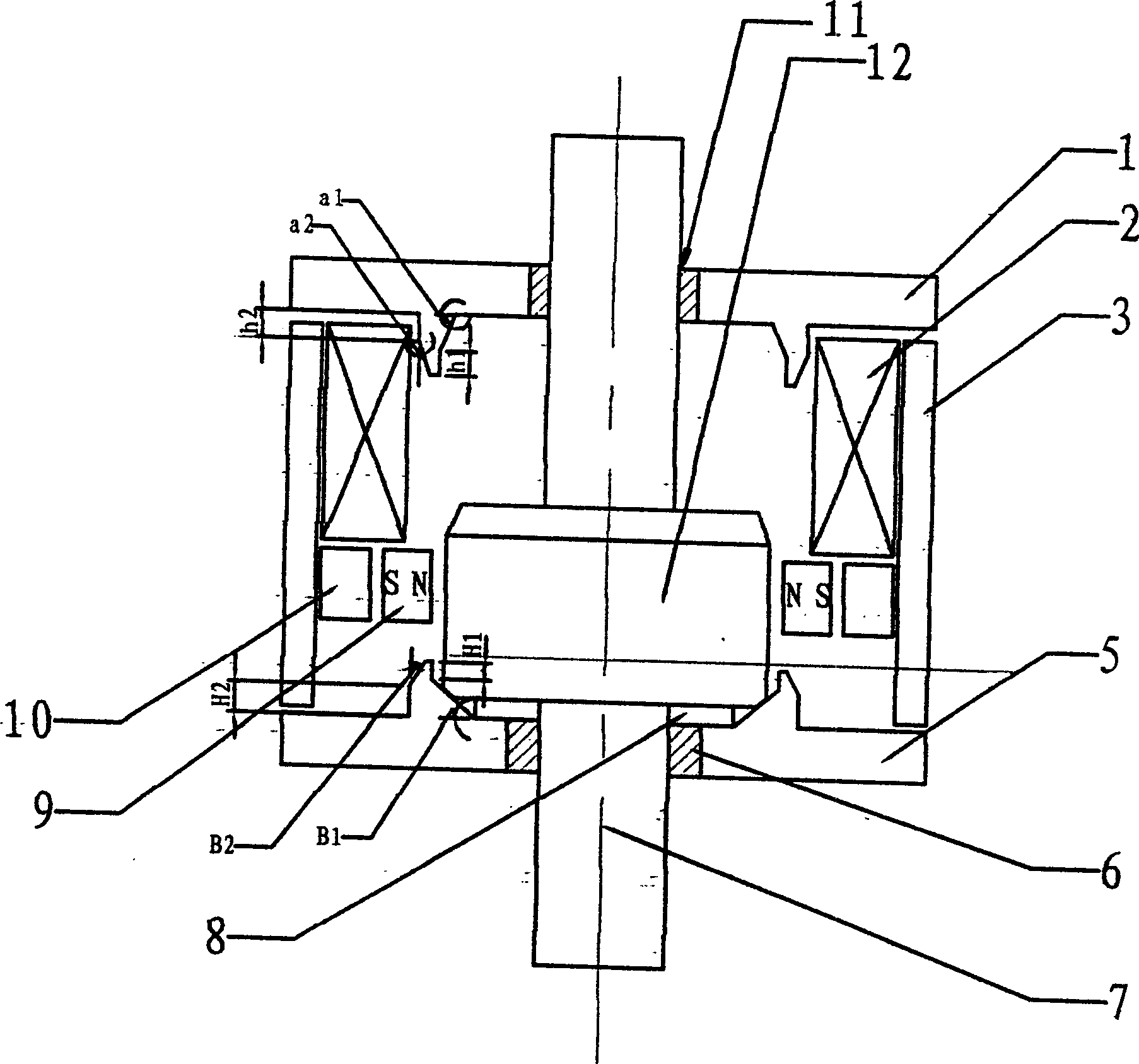
[0021] see figure 1 , figure 1 It is the first structure schematic diagram of the present invention.

[0022] According to the technical solution of the present invention, the permanent magnet mechanism includes: a transmission rod 7, an armature 12 is arranged on the transmission rod, and an opening coil 4, a permanent magnet 9, a pole shoe 10, and a closing coil are respectively arranged around the armature 12. 2 and the static iron core 3, the upper and lower ends of the transmission rod 7 pass through the upper and lower bushings 11, 6, the upper and lower bushings are respectively inlaid on the upper end cover 1 and the lower end cover 5, and an auxiliary gasket 8 is installed on the lower end cover 5 , The upper end cover 1 is a pot-shaped structure, and the bevel angle in the pot is the same as the taper angle of the armature 12 .

Embodiment 2

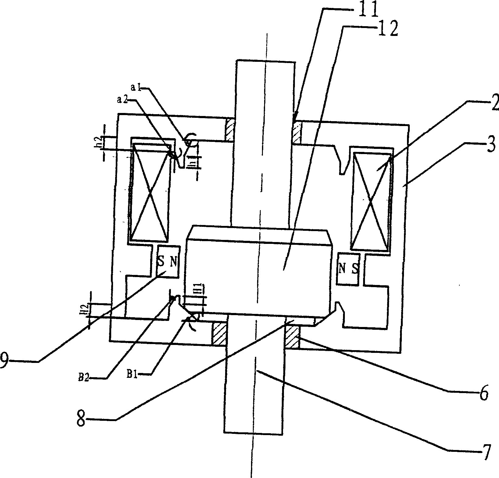
[0024] figure 2 It is the second structure schematic diagram of the present invention. The difference between this embodiment and Embodiment 1 is that this embodiment adopts a square structure. In the square structure, the upper and lower end covers 1, 5 and their attached basin shapes, the static iron core 3 and the pole shoe 10 are made into a whole, and are collectively called the static iron core. Simultaneously, the auxiliary gasket 8 and the armature 12 are also made into corresponding square shapes. All the other are with embodiment 1.

Embodiment 3

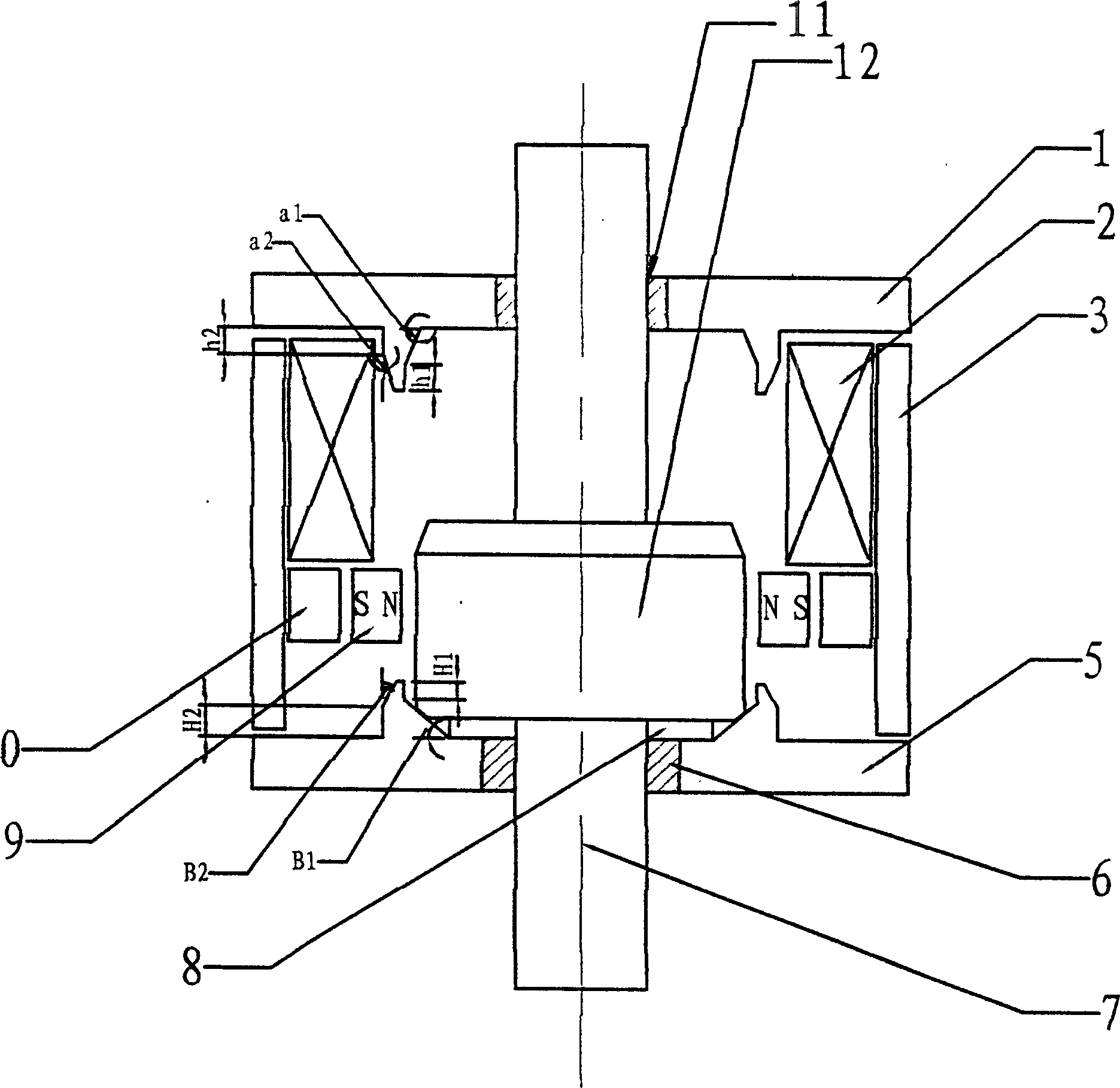
[0026] image 3 It is the third structural diagram of the present invention. The difference between this embodiment and Embodiment 1 is that the opening coil 4 is removed around the armature 12, and the rest are the same as in Embodiment 1, only relying on the internal communication of the closing coil 2 to communicate with the The current in the opposite direction of the closing current to complete the opening operation. However, this structure will produce a certain demagnetization effect on the permanent magnet, and the purpose of Embodiment 1 can also be achieved under certain less demanding conditions.


PUM


Abstract

The operating and driving mechanism applied to the driving mechanism in the breaker and switch disconnector etc. equipment includes following structure. The armature is fixed on the driving rod. The coil for detaching breaker (some time it can be left out), the permanent magnet, the pole shoes, the closing coil and the static iron core are set up around the circumference of the armature. The upper and the lower ends of the driving rod pass through the upper and the lower axial sleeves, which are inserted into the top end cover and the bottom end cover. There is the asistance mat slice on the bottom end cover. The top end cover is in the basin-typed structure. The static iron core, the top and the bottom end covers as well as the pole shoes can be made as the integrated piece.

Description

1. Technical field [0001] The invention belongs to the field of medium and low voltage switches, and relates to a permanent magnet operating mechanism applied to medium and low voltage switches such as circuit breakers and load switches. 2. Background technology [0002] In the field of medium and low voltage switches, two kinds of switch operating mechanisms are generally used now. One is a spring energy storage type operating mechanism, and the other is an electromagnetic operating mechanism. In the actual use of the former, due to factors such as complex structure, many moving parts, large energy storage noise, high production process requirements, and low overall reliability, the switch sometimes refuses to move due to parts breakage, corrosion, out-of-stock, and stagnation. occur. And the latter, though simple in structure, still has the higher take-off, locking device of failure rate, and requires bigger operating work. Although the existing permanent magnet operati...

Claims


Application Information

Patent Timeline
Patent Type & Authority Applications(China)
IPC IPC(8): H01H3/22H01H71/10H01H71/66
Inventor 郑士泉陈赤汉杨文海陈德桂
Owner 西安通大思源电器有限公司
Why Eureka
Try Eureka