
Probe card for LCD detection

A probe card and stylus technology, which is applied to coupling devices, measuring device casings, instruments, etc., can solve problems such as complicated operations, thickening of the guide plate 5, and inability to accurately identify the state of the stylus insertion groove 5a

Inactive Publication Date: 2003-05-14
MICO LTD
View PDF2 Cites 7 Cited by
  • Summary
  • Abstract
  • Description
  • Claims
  • Application Information

AI Technical Summary

Problems solved by technology

[0014] However, in this structure, the thickness of the guide plate 5 will be excessively thickened. In order to make the two guide plates 5 bonded to form a stacked layer structure, the operation becomes too complicated and other inconveniences.
[0015] In particular, when the stylus insertion groove 5a is formed on the guide plate 5, the processing depth (approximately 500 μm) is formed too deep, so there is a problem that the so-called confirmation of the workability by a microscope is inaccurate.
[0016] That is, the depth seen through a microscope is about 170 to 300 μm, and since the above-mentioned structure is formed at a depth of about 500 μm, it is impossible to accurately check the degree of processing in the state where the stylus insertion groove 5d is processed.
[0017] As a result, the state of the installation surface of the stylus insertion groove 5a cannot be accurately recognized, so that the insertion state of the stylus plate 6 becomes uneven, resulting in a poor assembly state.
[0018] Moreover, in the patented invention, since both ends of the guide plate 5 on the side of the LCD connection end 6a and the substrate connection end 6b of the stylus board 6 are completely open toward the outside, a so-called stylus board 6 may occur. The deflection and deformation of the connecting ends 6a and 6b will cause problems such as poor contact

Method used


Image

  • Probe card for LCD detection
  • Probe card for LCD detection
  • Probe card for LCD detection

Examples


Embodiment Construction

[0034] Hereinafter, embodiments of the present invention will be described in detail using the drawings.

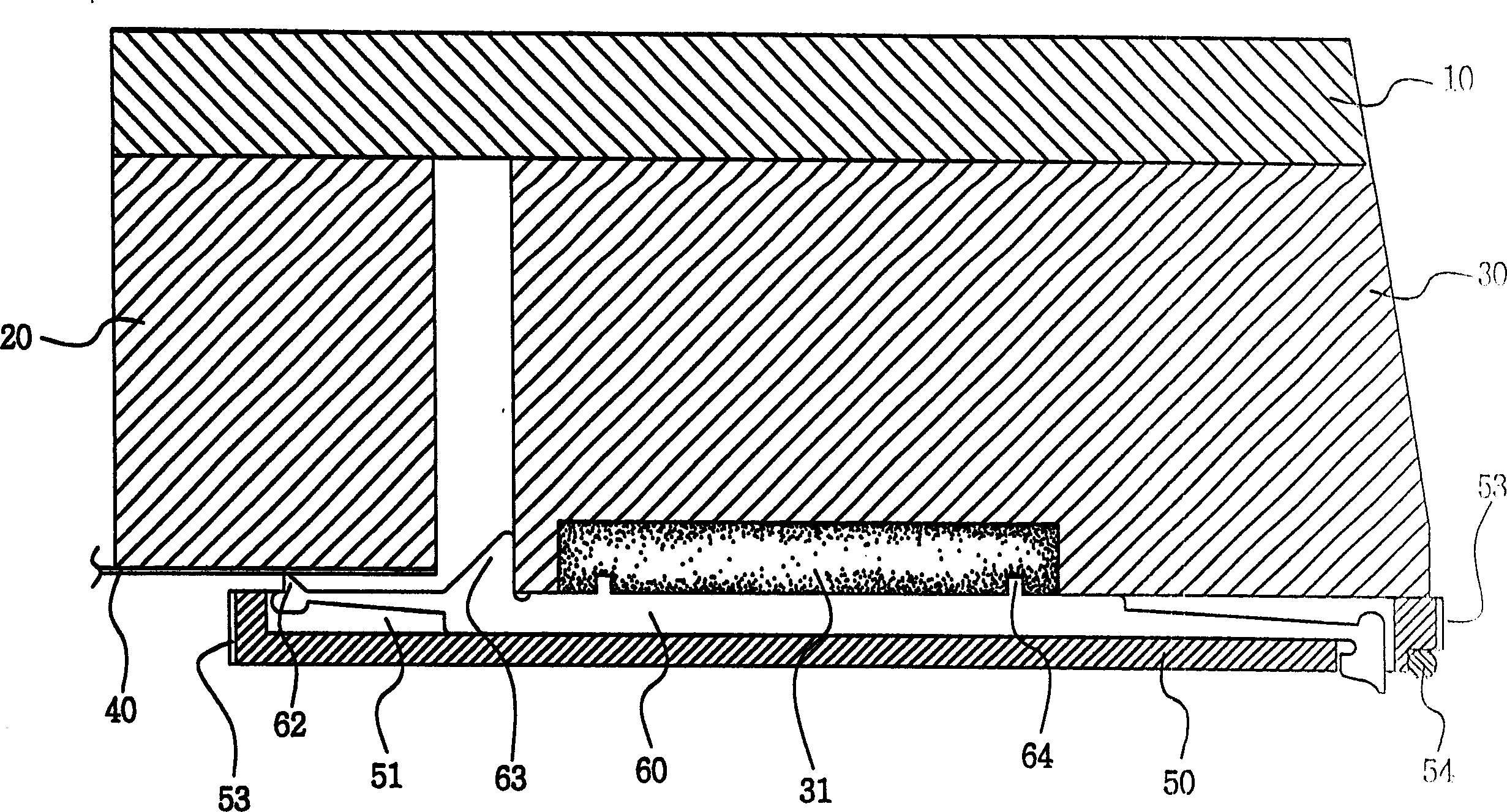
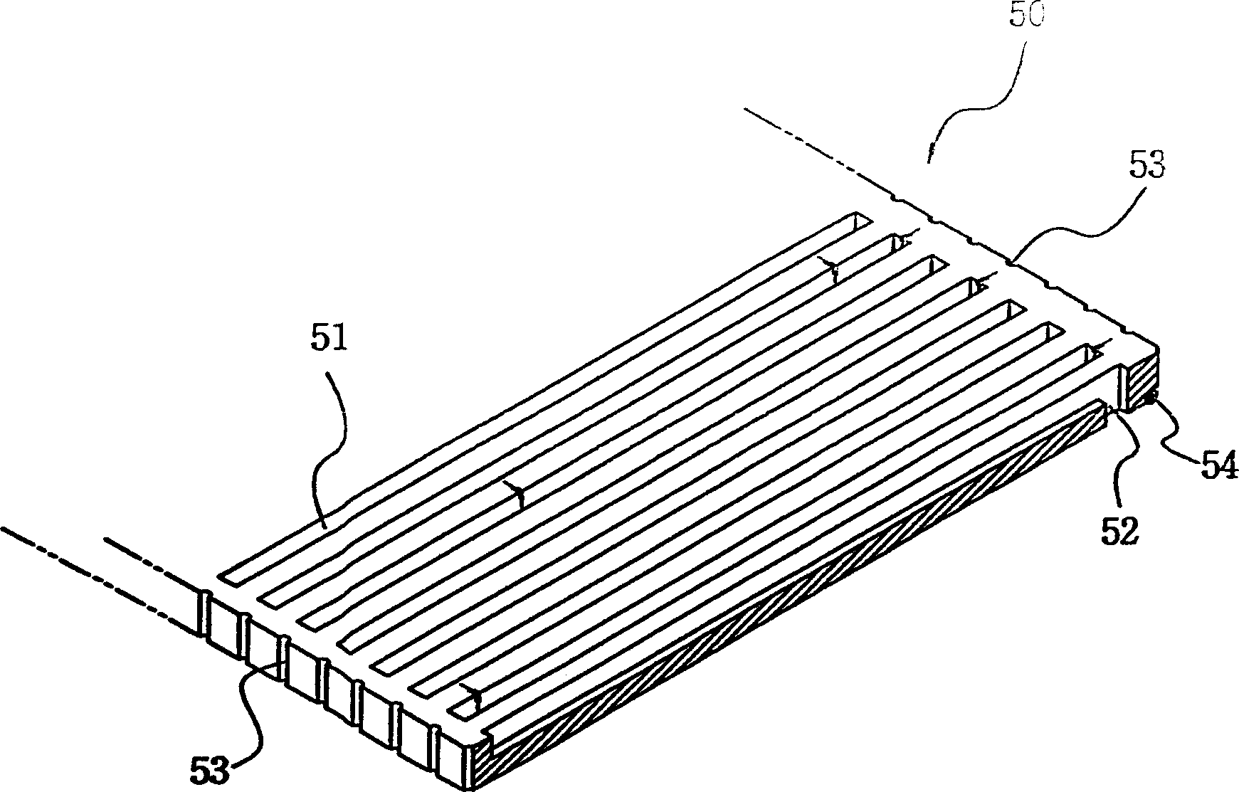
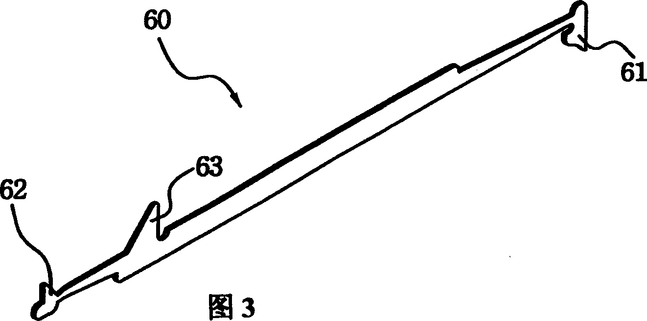
[0035] The present invention is characterized in that the guide plate has a silicon plate of the same material as the known chip, and at the same time it is thinned, and the stylus insertion groove is obtained by patterning in the above silicon plate, and the depth of the stylus insertion groove can be formed. It is possible to check the degree of processing of the stylus insertion groove to the extent that the microscope can identify it, and to prevent deflection and deformation of the connecting ends on both end sides of the stylus plate inserted into the stylus insertion groove.

[0036] The present invention as figure 1 As shown, a base plate base 20 is connected and fixed on one side of the assembly base 10 and the bottom surface of the assembly base 10 , and a stylus base 30 is provided on the other side corresponding to the base base 20 to form a structure similar...


PUM

PropertyMeasurementUnit
Depthaaaaaaaaaa

Abstract

The present invention provides a probe card for testing a liquid crystal display which is consisted of an assembly holder, a substrate holder, a needle holder, a circuit substrate with driver IC thereon that is sticked on the upper surface, a guide plate sticked at the bottom surface of the needle holder which is consist of a plurality of needle insert trench formed on the upper surface and an align trench formed at the outer surface of two side and parallel to the needle insert trench and is formed through the needle insert trench, and a needle plate inserted to the needle trench of guide plate which is flexible at two end, one end of the needle plate is through the guide hole formed on the guide plate to form an LCD connect end, the another end of the needle plate is stand out the upper surface of guide plate to form substrate connect end, and the needle plate connect to the outside surface of the needle holder that is stand out the upper surface of back end of needle holder to form a salient.

Description

technical field [0001] The present invention relates to a probe card for LCD inspection, and more particularly to a probe card that reduces the thickness of a guide plate made of silicon material that supports the stylus board by reducing the insertion thickness of the stylus board, thereby saving manufacturing costs. At the same time, it promotes the thinning of the probe card; in particular, it is a probe card for LCD inspection that can improve the efficiency of LCD performance inspection by stably protecting each connection terminal of the probe board that contacts the circuit pattern. Background technique [0002] Generally speaking, as image display devices such as small TVs and notebook computers, LCDs (liquid crystal display devices) are mainly used. The edges of the LCDs are provided with high-density devices for applying electrical signals (such as image signals, synchronization signals, and color phases). Signals, etc.) with tens or even hundreds of connection ter...

Claims


Application Information

Patent Timeline
IPC IPC(8): G01R1/073G01R1/04G01R31/00G02F1/13G02F1/1345H01L21/66
CPCG01R1/07307H01R33/94
Inventor 田泰云
Owner MICO LTD
Learn More