RF coil system for magnetic resonance image forming device

A technology of magnetic resonance imaging and radio frequency coils, applied in magnetic resonance measurement, application, communication between multiple stations, etc., can solve time-consuming and time-consuming problems, and achieve the effect of optimizing the structure

Inactive Publication Date: 2003-05-28
KONINKLIJKE PHILIPS ELECTRONICS NV
View PDF0 Cites 35 Cited by
  • Summary
  • Abstract
  • Description
  • Claims
  • Application Information

AI Technical Summary

Problems solved by technology

This step can be very time consuming, and it will be even more time consuming if the patient has to be removed from the MR unit multiple times

Method used


Image

  • RF coil system for magnetic resonance image forming device
  • RF coil system for magnetic resonance image forming device
  • RF coil system for magnetic resonance image forming device

Examples


Embodiment Construction

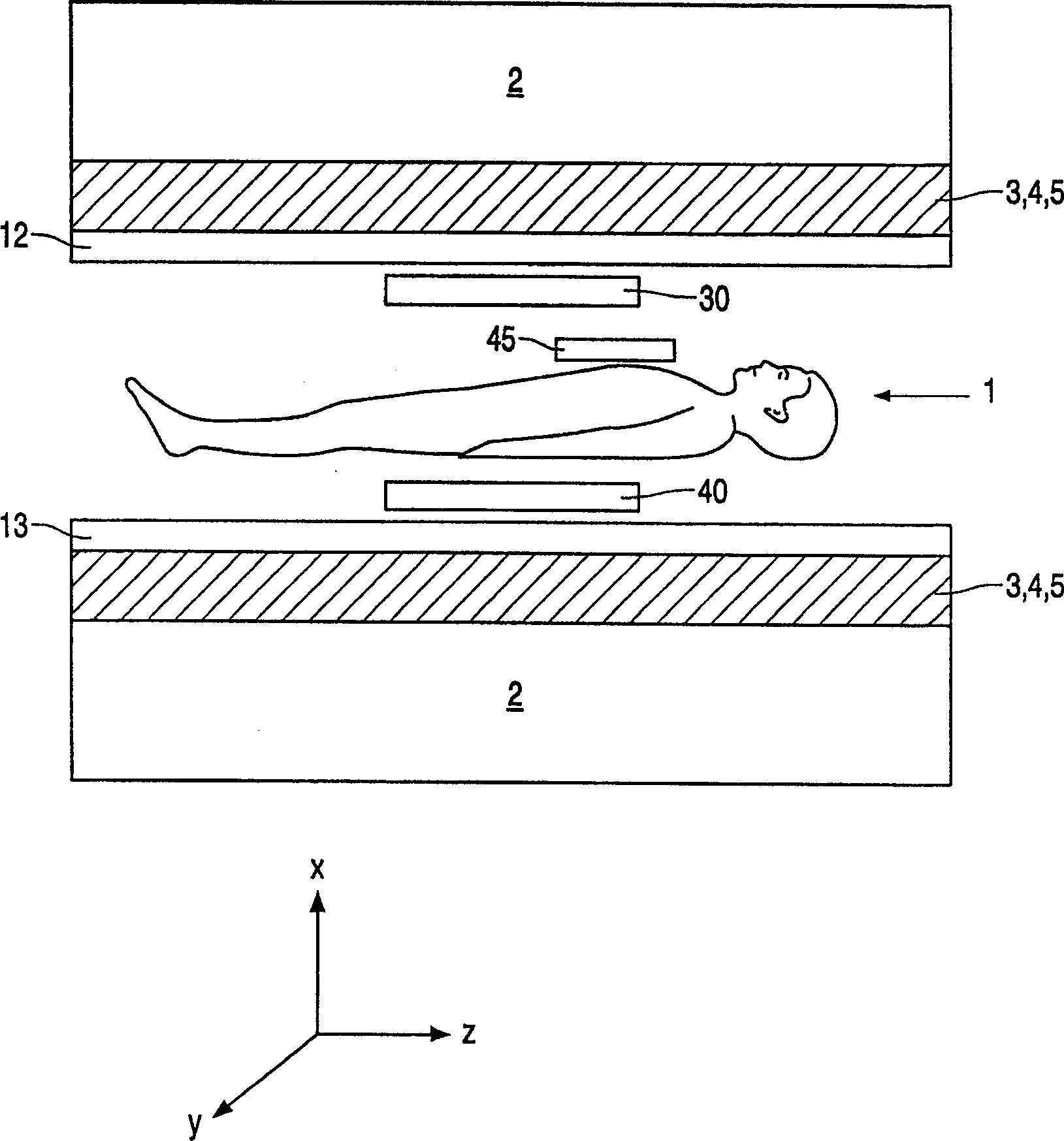
[0036] figure 1 is a longitudinal cross-sectional schematic diagram of a magnetic resonance imaging device (MR detection device) including a tubular detection space (axial system). A measured object 1, such as a patient, is located in the detection space. The detection space is surrounded by electromagnetic coil 2, which is used to generate a uniform and stable basic magnetic field (B 0 The magnetic field or the main magnetic field is used to magnetize the target to be measured, that is, to adjust the nuclear spin), the basic magnetic field runs through the detection space along the axial direction (z direction), and the magnitude of the magnetic flux density (magnetic induction) ranges from tens of Tesla to several Tesla.

[0037] For spatial identification and resolution of signals emitted by the measured object 1 , the detection space is surrounded by three gradient magnetic field coils 3 , 4 , 5 (not shown in detail), which generate three gradient magnetic fields extendi...


PUM


Abstract

An RF coil system for a magnetic resonance imaging apparatus whereby a substantially computer-aided and hence automatically optimized image quality in respect of signal-to-noise ratio and resolution can be achieved in dependence on the type and size of the object to be imaged, without time-consuming replacement or manual positioning of the RF coil system being necessary. To this end, the coil system (A) includes a plurality of single RF coils (Sx) which are essentially decoupled from one another and have a different size and / or different position, as well as a control device with a plurality of transmission units which are associated with a respective RF coil and whereby one or more RF coils can be selected and supplied with an RF pulse having an independently adjustable amplitude and / or phase and / or pulse shape. The invention also relates to a magnetic resonance imaging apparatus provided with such an RF coil system.

Description

technical field [0001] The present invention relates to a radio frequency (RF) coil system for a magnetic resonance imaging apparatus, and to such a magnetic resonance imaging apparatus. Background technique [0002] Magnetic resonance imaging (MRI) devices are used in particular to examine and treat patients. The nuclear spins of the examined tissue are thus aligned by the basic magnetic field and excited by the RF pulses. The RF relaxation process thus induced is then subjected to gradient magnetic field induction, which is received and processed to form an image of the detection region. [0003] There is a certain difference between the so-called open MR system (vertical system) and the MR system. In the open MR system, the patient is placed in the detection area formed between the two ends of the C-shaped bracket. The individual measuring surfaces are close to the patient, while the MR system contains a tubular examination area (axial system) in which the patient is pl...

Claims


Application Information

Patent Timeline
Patent Type & Authority Applications(China)
IPC IPC(8): G01R33/32G01R33/36H04B7/26
Inventor C·G·罗伊斯勒
Owner KONINKLIJKE PHILIPS ELECTRONICS NV
Why Eureka
Try Eureka