Hydraulic steel bar cutting machine

A steel bar cutting machine and hydraulic technology, which is applied in the field of hydraulic steel bar cutting machines, can solve the problems of large volume of motorized steel bar cutting machines, low working efficiency of manual steel bar cutting machines, inconvenient operation, etc., and achieves low noise, good lubrication and convenient operation. Effect

Inactive Publication Date: 2003-06-04
张永生
View PDF0 Cites 10 Cited by
  • Summary
  • Abstract
  • Description
  • Claims
  • Application Information

AI Technical Summary

Problems solved by technology

[0003] The invention aims to solve the shortcomings of low working efficiency of the manual steel bar cutting machine and the large volume and inconvenient operation of the motorized steel bar cutting machine, and provides an electric hydraulic steel bar cutting machine capable of realizing automatic and semi-automatic cycle control

Method used


Image

  • Hydraulic steel bar cutting machine
  • Hydraulic steel bar cutting machine
  • Hydraulic steel bar cutting machine

Examples


Embodiment Construction

[0020] Referring to the attached picture:

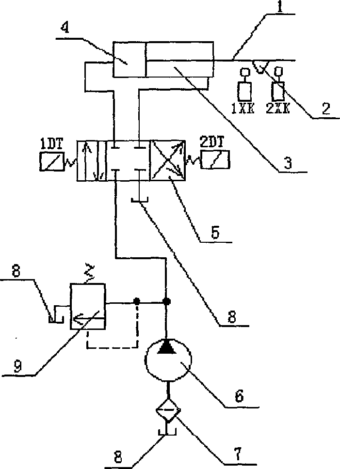
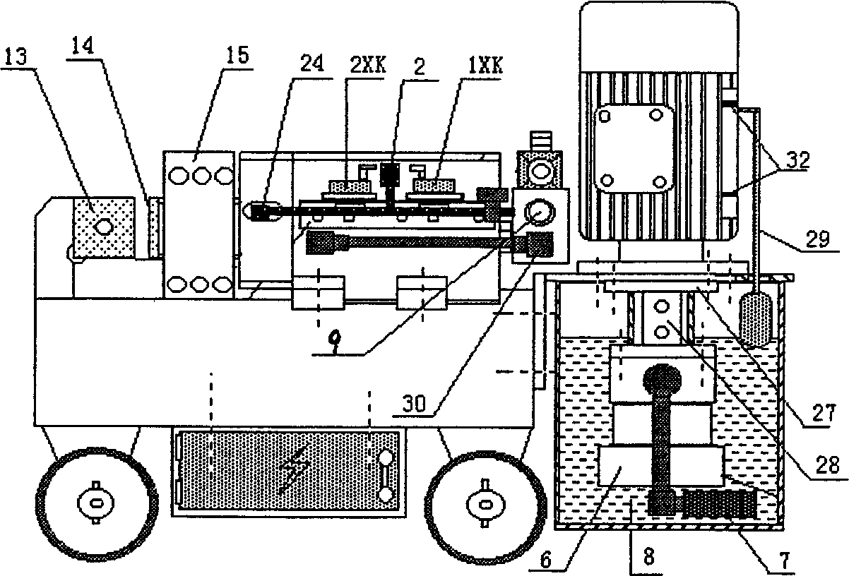
[0021] The hydraulic steel bar cutting machine of the present invention comprises a machine base 17, a knife seat 13, a hydraulic cylinder 16 with a piston rod 1, a piston rod guide seat 15, and a cutting blade 14 is fixed on the piston rod. There is a seal 26 between the hydraulic cylinders 16 .

[0022] It also includes an oil pump 6 driven by a motor 21. The output pipe of the oil pump 6 is connected to the front chamber 3 and the rear chamber 4 of the hydraulic cylinder through the oil separator 18; ;

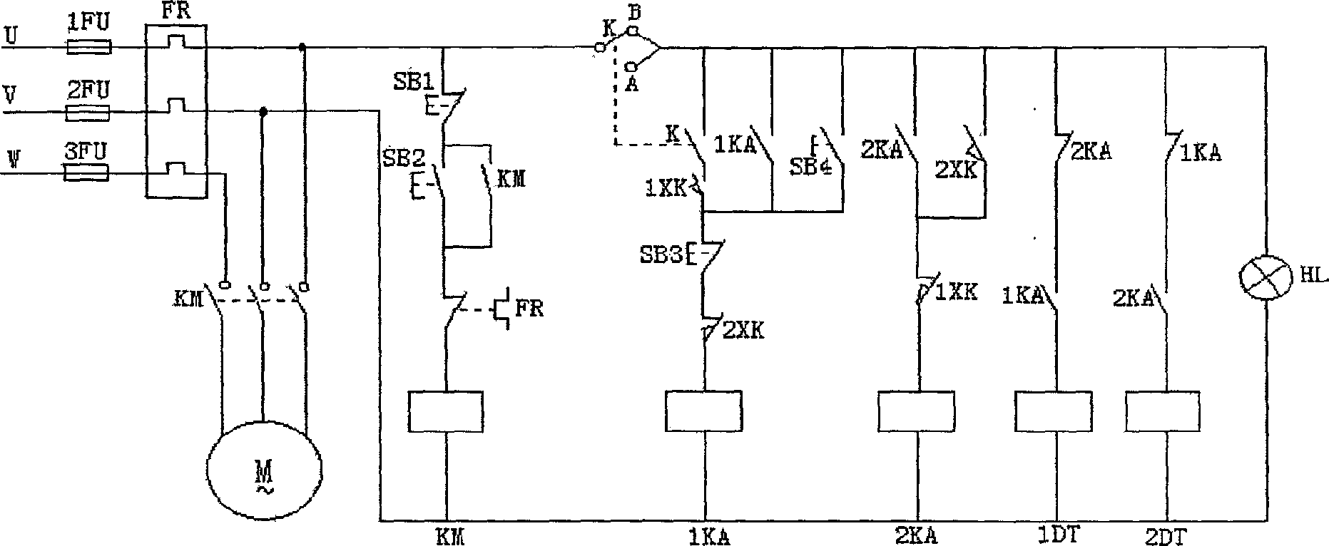
[0023] The electromagnetic reversing valve 5 for switching the oil circuit is installed on the oil distributor 18, and the electromagnetic reversing valve 5 has a first electromagnet 1DT for controlling the oil delivery pipeline in the rear chamber 4 of the hydraulic cylinder and a first electromagnet 1DT for controlling the oil delivery pipeline in the front chamber 3 of the hydraulic cylinder. Two electromagnets 2DT;

[0024]...


PUM


Abstract

The hydraulic steel bar cutting machine includes machine base, cutter seat, hydraulic cylinder with piston rod, piston rod guiding seat, cutter fixed on the piston rod, sealing part between the piston rod and the hydraulic cylinder; motor driven oil pump connected via oil divider to the front cavity and the back cavity of the hydraulic cylinder, oil returning pipe connected between oil divider and oil tank; electromagnetic change-over valve with two electric magnets to control the front cavity and the back cavity separately; two stroke switches for limiting the range of the piston rod and corresponding touch blocks on the piston rod; and one circular control mechanism comprising the two stroke switches and the two electric magnets.

Description

(1) Technical field [0001] The invention relates to a hydraulic steel bar cutting machine. (2) Background technology [0002] There are two types of steel bar cutting machines sold and used in the market: manual and motorized. Manual steel bar cutters generally cut steel bars through the action of leverage, which has low work efficiency and high labor intensity, and it is difficult to cut larger steel bars. Motorized steel bar cutting machine generally cuts steel bars under the action of motor, belt, gear and eccentric shaft transmission, which is inconvenient to operate, large in size, inconvenient in transportation, loud in noise, strong in vibration, easy to wear on gears, easy to wear on belts, etc. (3) Contents of the invention [0003] The invention aims to solve the shortcomings of low working efficiency of manual steel bar cutting machine and large volume and inconvenient operation of motorized steel bar cutting machine, and provides an electrohydraulic steel bar ...

Claims


Application Information

Patent Timeline
Patent Type & Authority Applications(China)
IPC IPC(8): B21F11/00
Inventor 张永生
Owner 张永生
Why Eureka
Try Eureka