Motor driving device and method thereof

A motor-driven, motor technology, applied in the direction of the stopped device, etc., can solve the problems of inaccurate stop position of the motor, difficult reversal detection, long time required, etc., to achieve the effect of noise, smooth switching, and noise reduction

Inactive Publication Date: 2003-06-11
PANASONIC CORP
View PDF1 Cites 14 Cited by
  • Summary
  • Abstract
  • Description
  • Claims
  • Application Information

AI Technical Summary

Problems solved by technology

When the short-circuit braking mode is used, the noise of the motor M1 will not be generated during braking, and because the braking force depends on the counter voltage, it is very effective at high-speed rotation, but the braking force of the brake also decreases as the rotational speed decreases. Therefore, it takes a long time to come to a complete stop
[0015] When the reverse braking mode is used, since the motor windings L1~L3 are driven in the opposite direction during deceleration, the braking force is stronger, but the noise during high-speed rotation caused by phase deviation is relatively high
In addition, high-precision reverse detection is difficult. When the moment when the energization control signal S8 of the opposite polarity is stopped lags, even after the motor M1 stops, it will still drive in the opposite direction for a period of time, resulting in rotation in the opposite direction.
After that, although the energization control signal generating device 70D stops energizing the three-phase motor windings L1 to L3, the motor M1 will continue to rotate due to inertia, which not only takes a long time until it stops completely, but also makes the stop position of the motor inaccurate.

Method used


Image

  • Motor driving device and method thereof
  • Motor driving device and method thereof
  • Motor driving device and method thereof

Examples


Embodiment 1

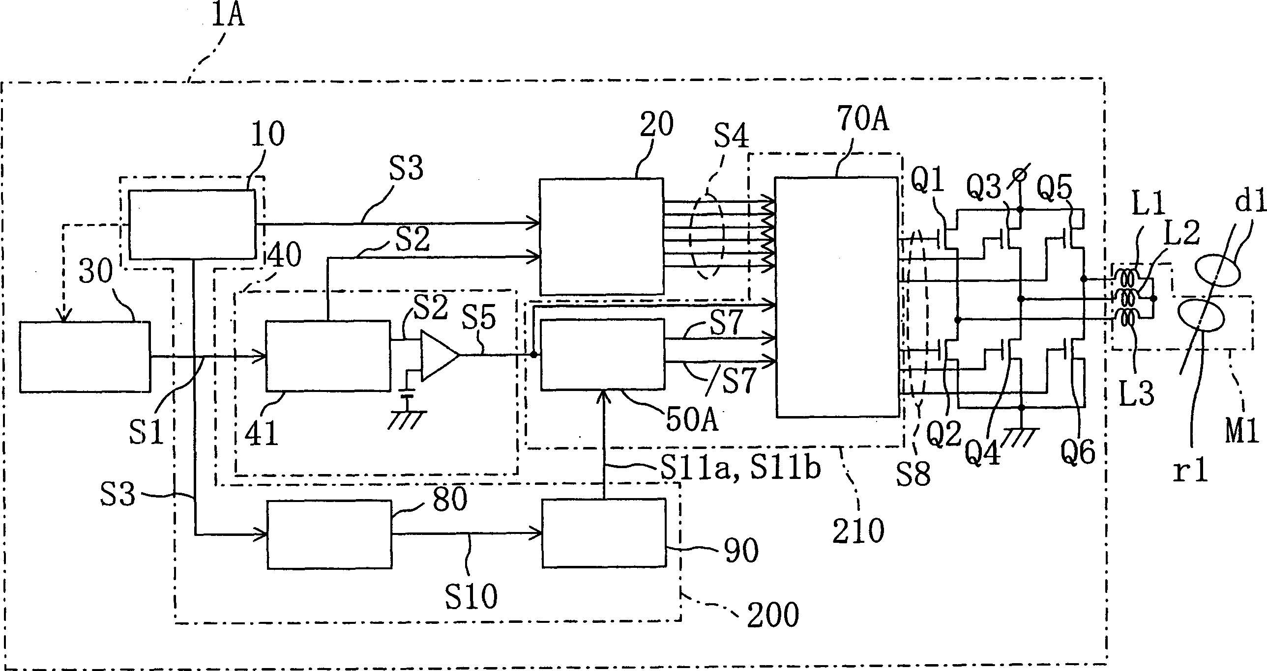
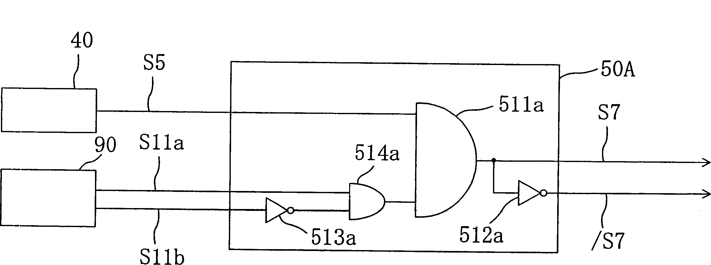
[0048] figure 1 It is a figure showing the structure of the motor drive apparatus 1A of Example 1 of this invention.

[0049] figure 1 The shown motor drive device 1A, like the conventional example, includes: a position detection device 10, an energization switching signal generating device 20, a rotation control device 30, a braking command generating device 40, a braking mode switching device 50A, an energizing Control signal generator 70A, and power transistors Q1 to Q6. It also includes: a rotation detection device 80 that detects the number of rotations per unit time of the rotor r1 based on the position signal S3 output by the position detection device 10 and outputs a signal S10 corresponding to the number of rotations; The number of rotations and the equivalent rotation identification device 90 whether the output signal S10 of the rotation detection device 80 reaches the preset reference value corresponding to the predetermined number of rotations. Further, outsid...

Embodiment 2

[0062] Figure 4 It is a figure which shows the structure of the motor drive apparatus 1B which concerns on Example 2 of this invention.

[0063] Figure 4 The motor drive unit 1B shown is in the figure 1 In addition to the components of the motor drive device 1A shown, a clock signal generating device 100 for supplying a clock signal S12 for switching the braking mode to the braking mode switching device 50B is provided.

[0064] Next, the operation of the motor drive device 1B configured as described above will be described.

[0065] The rotation detection device 80 detects the number of rotations of the rotor r1 per unit time according to the position signal S3 output by the position detection device 10 , and outputs a signal S10 corresponding to the number of rotations to the rotation identification device 90 . And, when the rotation identification device 90, when the signal S10 from the rotation detection device 80 is less than the reference value corresponding to the...

Embodiment 3

[0076] Figure 7 It is a diagram showing an example of a circuit configuration of a motor drive device according to Embodiment 3 of the present invention.

[0077] Figure 7 The motor drive device 1C shown is in the figure 1In addition to the constituent parts of the motor driving device 1A shown, a detection device 110 for detecting the current value after receiving the current value signal S13 indicating the current value of the current flowing through the motor windings L1 to L3, and The current value of the current value detection signal S14 from the current value detection device 110 is compared with a predetermined current value (reference value) set in advance and the current value identification signal S15 is output to the current value identification device 120 of the braking mode switching device 50C. .

[0078] Next, the operation of the motor drive device 1C configured as described above will be described.

[0079] The current value detection device 110, for e...


PUM


Abstract

Brake mode switching signal production means detects the number of revolutions per unit time of a rotor according to a change in a positional relationship between motor windings of a plurality of phases and the rotor so as to output first and second brake mode switching signals for selecting either a short brake mode or a reverse brake mode for braking the rotation of the rotor based on the number of revolutions. Control means outputs an energization control signal for controlling energization of the motor windings of a plurality of phases in response to the first and second brake mode switching signals. Thus, it is possible to reduce the braking noise and the stopping time.

Description

technical field [0001] The invention relates to a motor drive with a short-circuit brake and a reverse brake. Background technique [0002] As methods for stopping the motor, there are deceleration methods using a short-circuit brake and deceleration methods using a reverse brake. Moreover, the existing motor drive device has two modes: a short-circuit braking mode in which braking is performed by a short-circuit brake and a reverse braking mode in which braking is implemented by a reverse brake. deceleration and stop control. [0003] The motor deceleration method of the short-circuit braking mode adopts the method of forming a short-circuit circuit between the terminals of the 3-phase motor winding, and the motor deceleration method of the reverse braking mode adopts the method of supplying reverse current to the multi-phase motor winding. The current is driven in the reverse direction. [0004] Figure 9 It is a figure which shows the structure of the conventional moto...

Claims


Application Information

Patent Timeline
Patent Type & Authority Applications(China)
IPC IPC(8): H02P6/24
CPCH02P6/24
Inventor 村上真树
Owner PANASONIC CORP
Why Eureka
Try Eureka