Bearing device for driving wheel

A technology for driving wheels and bearing devices, applied in rolling contact bearings, bearings in rotating motion, bearings, etc., can solve problems such as failure to reach service life, and achieve the effect of satisfying service life, low cost, and inhibiting wear and tear.

Inactive Publication Date: 2003-07-02
NTN CORP
View PDF1 Cites 21 Cited by
  • Summary
  • Abstract
  • Description
  • Claims
  • Application Information

AI Technical Summary

Problems solved by technology

However, in the endurance test against bending moment carried out by the present applicant, it was judged that only by shortening the length of the plastic joint part to a length satisfying the allowable torque transmission, the desired life cannot be achieved.

Method used


Image

  • Bearing device for driving wheel
  • Bearing device for driving wheel
  • Bearing device for driving wheel

Examples


Embodiment Construction

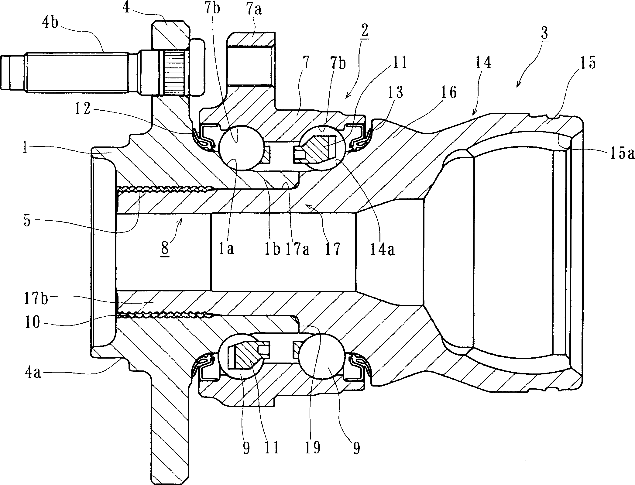
[0057] Hereinafter, embodiments of the present invention will be described in detail with reference to the drawings. figure 1 It is a longitudinal sectional view showing the first embodiment of the bearing device for driving wheels of the present invention.

[0058] Such a bearing device for a drive wheel is composed of a wheel hub 1 , a plurality of rows of rolling bearings 2 , and a universal constant velocity joint 3 . In addition, in the following description, in the state assembled to the vehicle, the side closer to the outer side of the vehicle is referred to as the outer side (left side in the figure), and the side closer to the center is referred to as the inner side (the left side in the figure). on the right side of the ).

[0059] The wheel hub 1 integrally has a wheel mounting flange 4 for mounting a wheel (not shown) on the end of the outer side, and it is useful to erect the wheel mounting flange 4 at equally divided positions in the circumferential direction. ...


PUM


Abstract

A bearing apparatus for a driving wheel of a vehicle is provided to promote reduction in the weight and size of the apparatus, suppress excessive stress or wear, and improve the durability. In a bearing apparatus for a driving wheel of a vehicle, a hub wheel(1), a constant velocity universal joint(3), and a double row rolling bearing(2) are assembled as a unit. One(1a) of the inner raceway surfaces in the double row rolling bearing is formed on the outer circumferential surface of the hub wheel, and the other(14a) of the inner raceway surfaces is formed on the outer circumferential surface of an outer joint member(14). The hub wheel and the outer joint member are fitted each other with one end surface(19) being abutted against a shoulder(16) of the outer joint member. The inner circumferential surface at the fitting portion of the hub wheel is formed with a hardened irregular portion(5). The hub wheel and the outer joint member are integrally connected via plastic deformation of the outer joint member with making the hardened irregular portion bite into the outer circumferential surface at the fitting portion of the outer joint member by radially outwardly expanding the fitting portion of the outer joint member. The outer circumferential surface of the outer joint member is formed with a hardened layer at least at a region including the inner raceway surface and a shaft portion(17) except for the fitting portion of the outer joint member.

Description

technical field [0001] The present invention relates to a drive wheel bearing device for supporting a drive wheel of an automobile, and more particularly, to a drive wheel bearing device in which a hub wheel, a universal joint, and a plurality of rows of rolling bearings are assembled. Background technique [0002] The rear wheels of a rear-wheel drive vehicle, the front wheels of a front-wheel drive vehicle, or all the wheels of a four-wheel drive vehicle are supported on the drive wheel bearing device through the suspension device. In recent years, efforts have been made to reduce the weight and size of bearing devices for drive wheels, and there is a tendency to assemble hub wheels, constant velocity joints, and bearings into assemblies. [0003] Figure 12 A vertical cross-sectional view of a conventional drive wheel bearing device is shown in which a wheel hub 50 , a plurality of rows of rolling bearings 60 , and a universal constant velocity joint 70 are assembled. Th...

Claims


Application Information

Patent Timeline
Patent Type & Authority Applications(China)
IPC IPC(8): B60B35/18B60B27/00F16C35/063
CPCF16C35/063B60B27/00Y02T10/86F16C43/04F16C33/60F16C2326/02F16C19/186F16C19/187F16C19/527B60B35/18
Inventor 小泽仁博田岛英児梅木田光小仓博幸
Owner NTN CORP
Why Eureka
Try Eureka