Filling up Teflon friction ring and its preparing method

A polytetrafluoroethylene and manufacturing process technology, applied in the field of friction rings, can solve the problems of short service life of friction rings and damage to the wear surface, and achieve improved service life, good cold flow resistance and wear resistance, and good self-lubrication. and thermal conductivity

Inactive Publication Date: 2003-07-23
广州宝力特液压技术有限公司
View PDF0 Cites 22 Cited by
  • Summary
  • Abstract
  • Description
  • Claims
  • Application Information

AI Technical Summary

Problems solved by technology

[0004] The purpose of the present invention is to overcome the disadvantages that the existing filled polytetrafluoroethylene friction rings are easy to cause damage to the matching grinding surface or the life of the friction ring is too short when used under the condition of no oil lubrication, and to provide a method that can reduce the friction of the matching grinding surface. Wear and improve service life of filled PTFE friction rings

Method used


Image

  • Filling up Teflon friction ring and its preparing method
  • Filling up Teflon friction ring and its preparing method
  • Filling up Teflon friction ring and its preparing method

Examples


Embodiment 1

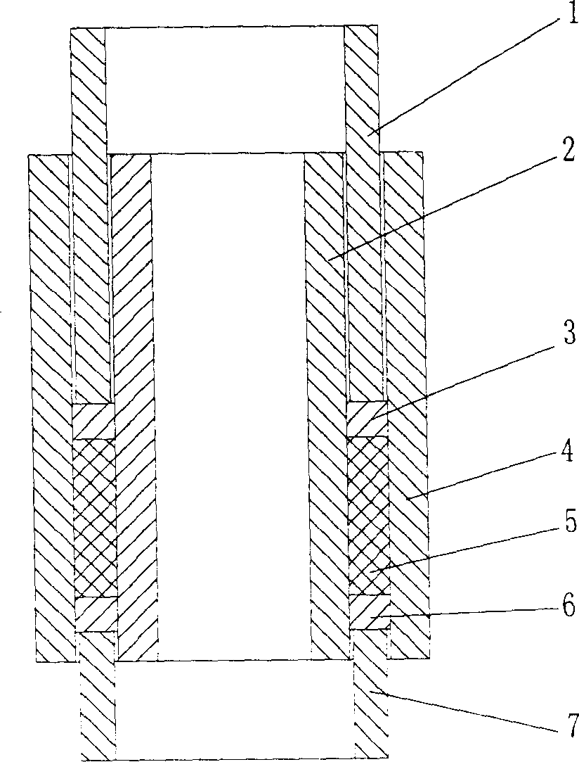
[0038] This filled PTFE friction ring is a friction ring used in a 4MPa reciprocating oil-free lubrication compressor. The specific working conditions are as follows: bore: 90mm, pressure: 4MPa, stroke: 180mm, operating temperature: ≤180℃, Medium: air, reciprocating frequency: 585min -1 ; The specific structure of the filled polytetrafluoroethylene friction ring is as follows Figure 5 ~ Figure 7 shown by Figure 5 ~ Figure 7 It can be seen that a shallow groove at a certain angle to the axis of the cylinder is machined on the outer circle and end surface of the friction ring. This groove can reduce the axial load of the friction ring. The herringbone shallow groove can make the torque formed by the axial force cancel each other out. Under the action of the torque formed by the oblique opening, the friction ring can rotate slowly along the circumferential direction, so as to achieve the purpose of uniform wear.

[0039] The type selection, composition and ratio of the filled...


PUM


Abstract

A filled friction ring of teflon for oiless lubricating is prepared from teglon (100 wt. portions), graphite (1-10%), carbon black (20-50%), glass fibre (0-30%) and MoS2 (0-5%) through mixing, die pressing under 40-70 MPa for 5-40 min, sintering and machining. Its advantages are high lubricating performance and long service life.

Description

technical field [0001] The invention relates to friction ring technology, in particular to a filled polytetrafluoroethylene friction ring and its manufacturing process and application. Background technique [0002] At present, the known manufacturing process of filled polytetrafluoroethylene friction rings includes process steps such as mixing, molding, sintering, and mechanical processing; Proportioning and mixing to make PTFE filler; Molding refers to placing PTFE filler in the mold, controlling its process parameters such as mold structure, pressure, pressure holding time, pressurization rate, etc., through a certain feeding-pressurization- Pressurization-relief-demolding procedure to make a molded semi-finished product; sintering refers to placing the molded semi-finished product in a sintering box, controlling its sintering temperature, heating rate, holding time, cooling rate, placement form and other process parameters, through a certain The...

Claims


Application Information

Patent Timeline
Patent Type & Authority Applications(China)
IPC IPC(8): C08J5/16C08L27/18
Inventor 吴德谦范清易荣何逢祥殷小平
Owner 广州宝力特液压技术有限公司
Why Eureka
Try Eureka