
Drive circuit of LCDs

A technology of liquid crystal display device and driving circuit, which is applied to static indicators, instruments, etc., can solve the problems of power multiplication, etc., and achieve the effects of reducing component costs, facilitating circuit design, and reducing the use of space

Inactive Publication Date: 2003-07-23
INVENTEC CORP
View PDF0 Cites 4 Cited by
  • Summary
  • Abstract
  • Description
  • Claims
  • Application Information

AI Technical Summary

Problems solved by technology

[0003] Common liquid crystal displays can be divided into: twisted nematic liquid crystal display (Twisted Nematic-LCD; TN-LCD), super twisted nematic liquid crystal display (Super TN-LCD; STN-LCD), double-layer super twisted nematic liquid crystal display ( Double layer STN-LCD; DSTN-LCD) and thin film transistor liquid crystal display (Thin Film Transistor-LCD; TFT-LCD) and other types, but in the process of liquid crystal display (LCM) work, often because must be in the same working cycle , to drive multiple sets of converters (Inverter) at the same time to maintain the work of multiple sets of cold cathode fluorescent lamps (Cold Cathode Fluorescent Lamp; CCFL), but the power consumed by the liquid crystal display device (LCM) is also doubled

Method used


Image

  • Drive circuit of LCDs
  • Drive circuit of LCDs
  • Drive circuit of LCDs

Examples


Embodiment Construction

[0029] The present invention will be further described below in conjunction with the drawings and embodiments:

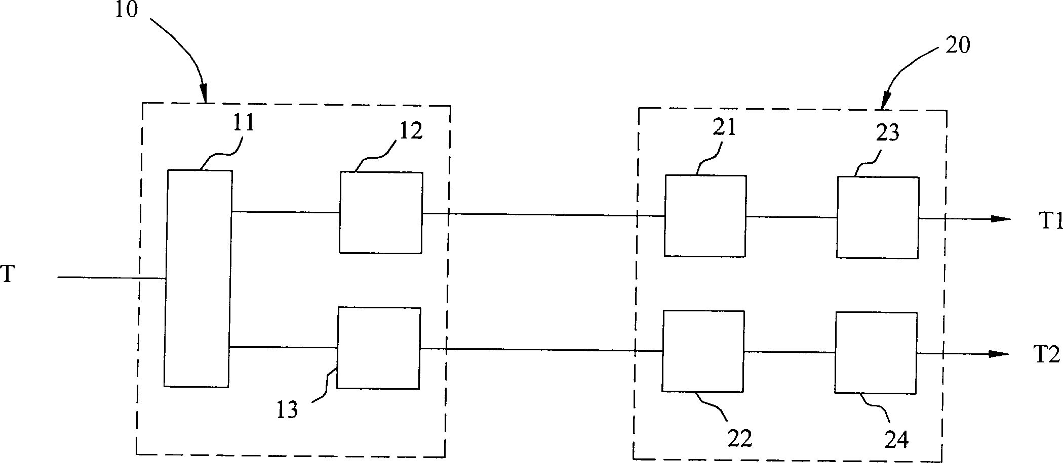
[0030] The present invention is a driving circuit of a liquid crystal display device, which is arranged in a liquid crystal display device (LCM), see figure 1 :

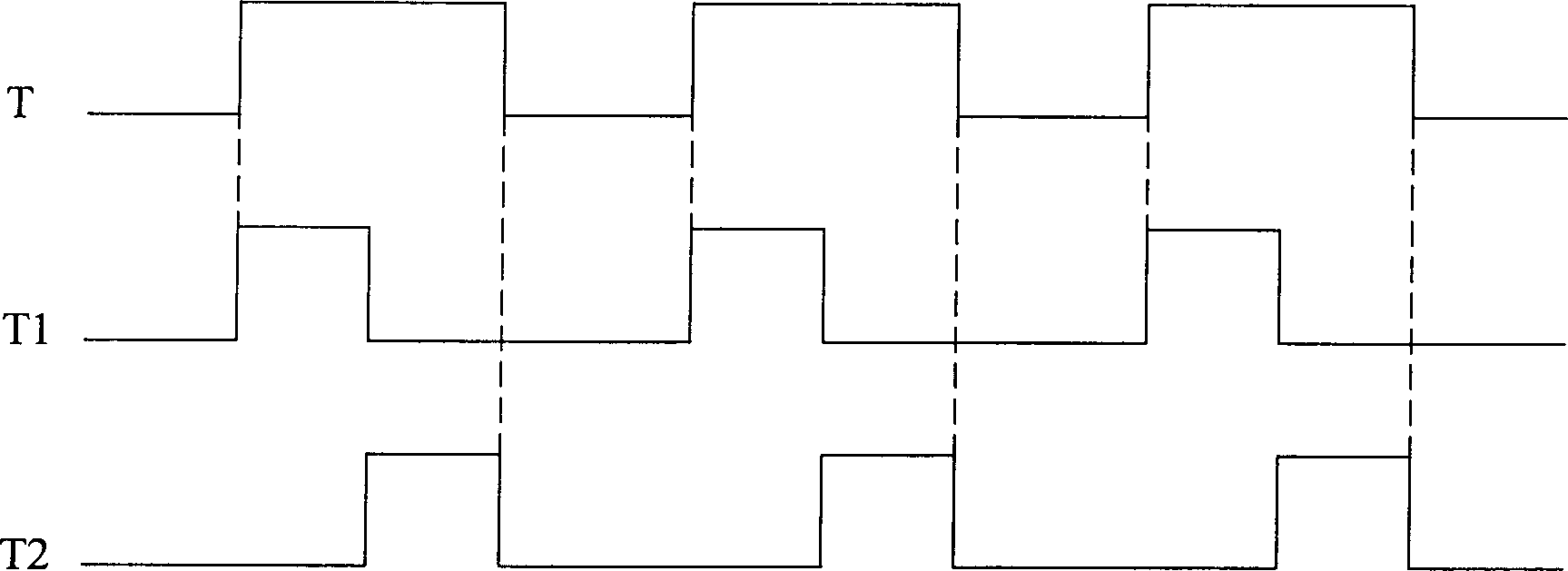
[0031] The driving circuit of the liquid crystal display device is a driving circuit that drives multiple groups of lamp tubes in an asynchronous manner. The lamp tube is a cold cathode fluorescent lamp (CCFL) of a liquid crystal display device (LCM). The driving circuit of the liquid crystal display device at least includes a driver The unit 10 and the transformer unit 20. The drive unit 10 is used to receive a duty cycle T, which is a cold cathode fluorescent lamp (CCFL) duty cycle of a liquid crystal display device (LCM). When the drive unit 10 is receiving the work In the period T, the operation period T is calculated, and after the operation is completed, a plurality of driving voltages are generated in ...


PUM


Abstract

The drive circuit includes the drive unit and the transformation unit. When multiple inverters are needed to drive LCD, the drive unit sands out the drive voltage in asynchronous mode to drive the transformation unit. With being magnified and converted by the transformation unit, the drive voltage is transmitted to the luminous tubes so as to reach the purpose of driving the LCD in same working cycle and in difference time sequence. Comparing with the cold cathode fluorescent lamp (CCFL), only one drive module is needed to generate the drive signal in the invention. The invention has the advantages of reducing space of the circuit uses. The invention can be widely used in LCD area.

Description

Technical field [0001] The present invention relates to a driving circuit, in particular to a driving circuit applied to a liquid crystal display device. Background technique [0002] With the development and popularization of electronic technology, the interface equipment of information processing devices has been continuously improved with the functions of information processing devices. Take display devices as an example. In the past, display devices were formed by heating the cathode of a filament to emit electrons, which were formed after acceleration and focusing. The cathode ray tube display (Cathode Ray Tube Monitor; CRTMonitor), which produces light spots or electrical signals after hitting the electron beam on the screen, has developed into today’s display device, that is, a rod that changes direction when subjected to current A rod-shaped crystal molecule (Liquid Crystal Display Module; LCM) to display information. [0003] Common liquid crystal displays can be divided...

Claims


Application Information

Patent Timeline
Patent Type & Authority Applications(China)
IPC IPC(8): G09G3/36
Inventor 游一清
Owner INVENTEC CORP
Learn More