Method by using wet etching with non-equivalence in directions to carry out even process

An anisotropic, wet etching technology, used in electrical components, semiconductor/solid-state device manufacturing, circuits, etc., to solve problems such as surface scratches, affecting components, and reducing component reliability.

Inactive Publication Date: 2003-07-23
MACRONIX INT CO LTD
View PDF0 Cites 4 Cited by
  • Summary
  • Abstract
  • Description
  • Claims
  • Application Information

AI Technical Summary

Problems solved by technology

However, due to the extremely high hardness of the above-mentioned abrasive particles, when chemical mechanical polishing is used to grind the surface of some materials, it is very easy to cause surface scratches, so that bridging (bridge) problems occur in the subsequent manufacturing process and affect the operation of the components. , resulting in reduced component reliability

Method used


Image

  • Method by using wet etching with non-equivalence in directions to carry out even process
  • Method by using wet etching with non-equivalence in directions to carry out even process
  • Method by using wet etching with non-equivalence in directions to carry out even process

Examples


Embodiment Construction

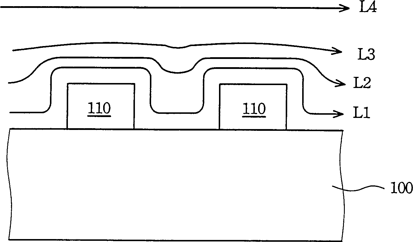
[0024] Please refer to figure 1 , figure 1 It is a schematic diagram of liquid flowing over a surface with uneven surface. There are protrusions 110 on the base 100, when the liquid flows through the surface of the base 100, according to the distance from the surface of the base 100 from near to far, in figure 1 The indicated flows are L1, L2, L3 and L4. The liquid flow L1 closest to the surface of the substrate 100 has the slowest flow velocity because it encounters the protrusion 110 on its flow path. On the contrary, the liquid flow L4 farthest from the surface of the substrate 100 has the fastest flow speed because it does not encounter any obstacles on its flowing path.

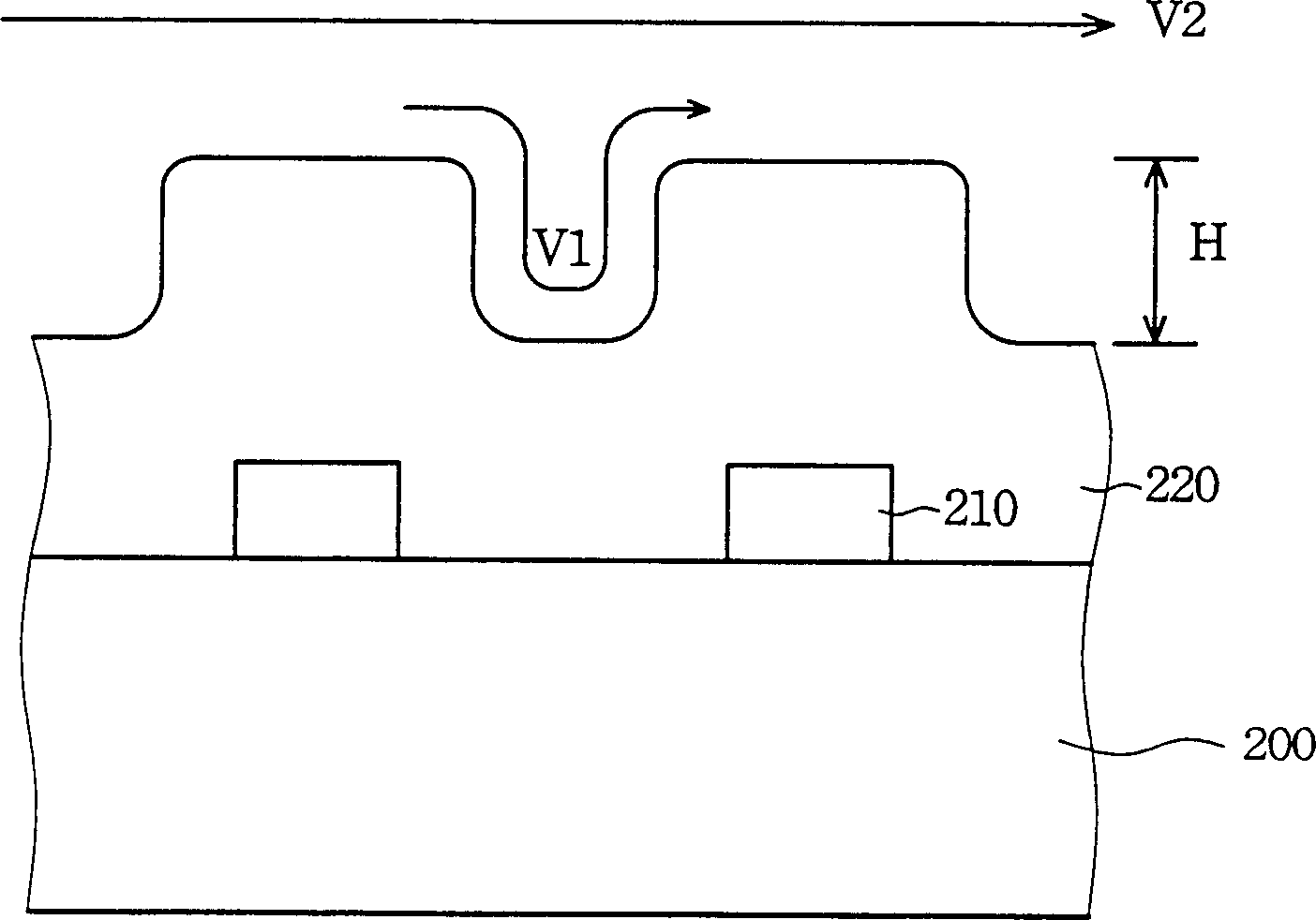
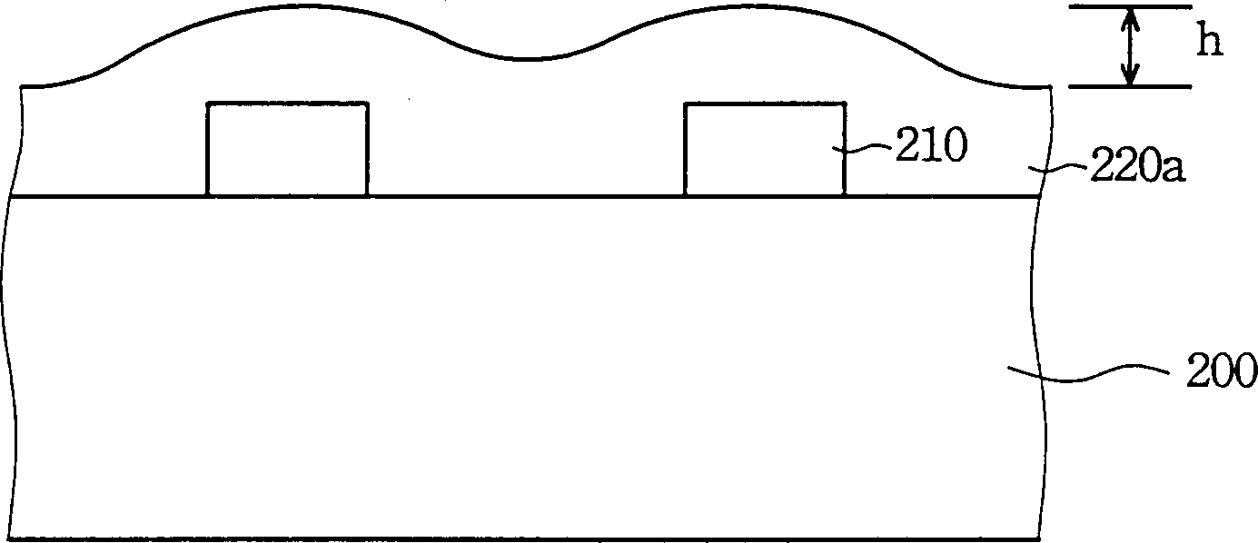
[0025] Please refer to Figure 2A-2B , which is a cross-sectional view showing a planarization process using an anisotropic wet etching method according to a preferred embodiment of the present invention. Please refer to Figure 2A , there is a wire 210 on the substrate 200, and the wire 210 can be...


PUM


Abstract

Sulfur acid, phosphoric acid, hydrofluoric acid and water are mixed to form the etching solution. Then, the substrate is put into the etching solution. The etching solution flows across the insulation layer on the substrate with proper velocity of flow. The insulation layer possesses multiple channels. The different velocities of flow of the etching solution on the accidental surface of the insulation layer make different etching speeds. The etching speed at the bulging is higher than the speed at the dishing so as to reach the goal of evenness.

Description

technical field [0001] The present invention relates to a method for planarization, and in particular to a method for planarization by anisotropic wet etching. Background technique [0002] When manufacturing multi-metal interconnects, usually two layers of metal wires must be separated by insulating materials in order to avoid short circuits. However, because the surface of the wafer fluctuates, the deposited insulating layer also fluctuates with the surface of the wafer. At this time, surface planarization becomes a decisive step for the smooth progress of the photolithography process for the next layer of metal lines. [0003] Therefore, in semiconductor manufacturing technology, surface planarization is an important technology for high-density photolithography. A flat surface with no height difference can avoid the problem of exposure scattering for precise pattern transfer (Pattern Transfer) steps. Chemical-Mechanical Polishing (CMP) is a technology that can now provi...

Claims


Application Information

Patent Timeline
Patent Type & Authority Applications(China)
IPC IPC(8): C23F1/16H01L21/306
Inventor 蔡文彬张庆裕吴俊沛陈辉煌潘正圣
Owner MACRONIX INT CO LTD
Why Eureka
Try Eureka