
Solenoid valve

A technology of solenoid valves and solenoid coils, applied in the field of solenoid valves, can solve problems such as defects, corrosion, and difficult handling

Inactive Publication Date: 2003-07-30
FUJIKOKI MFG CO LTD
View PDF1 Cites 11 Cited by
  • Summary
  • Abstract
  • Description
  • Claims
  • Application Information

AI Technical Summary

Problems solved by technology

This pickling effluent is environmentally harmful and difficult to dispose of, so special management is necessary
[0006] In addition, after assembling the plunger tube of the valve main body and the magnetic guide with the plunger and coil spring, etc., apply flux to the silver solder on the welding part of the magnetic guide, and use high-frequency welding to make the silver solder adhere. Cleaning by washing or pickling, etc., may cause corrosion due to residual flux, and flux may flow into the valve, causing poor operation of the plunger tube or clogging due to contamination of the cooling system.
[0007] In addition, due to the use of fixtures between the tube and the suction body, there are problems with difficult liquid circulation, delayed or poor plunger tube action

Method used


Image

  • Solenoid valve
  • Solenoid valve
  • Solenoid valve

Examples


Embodiment 1

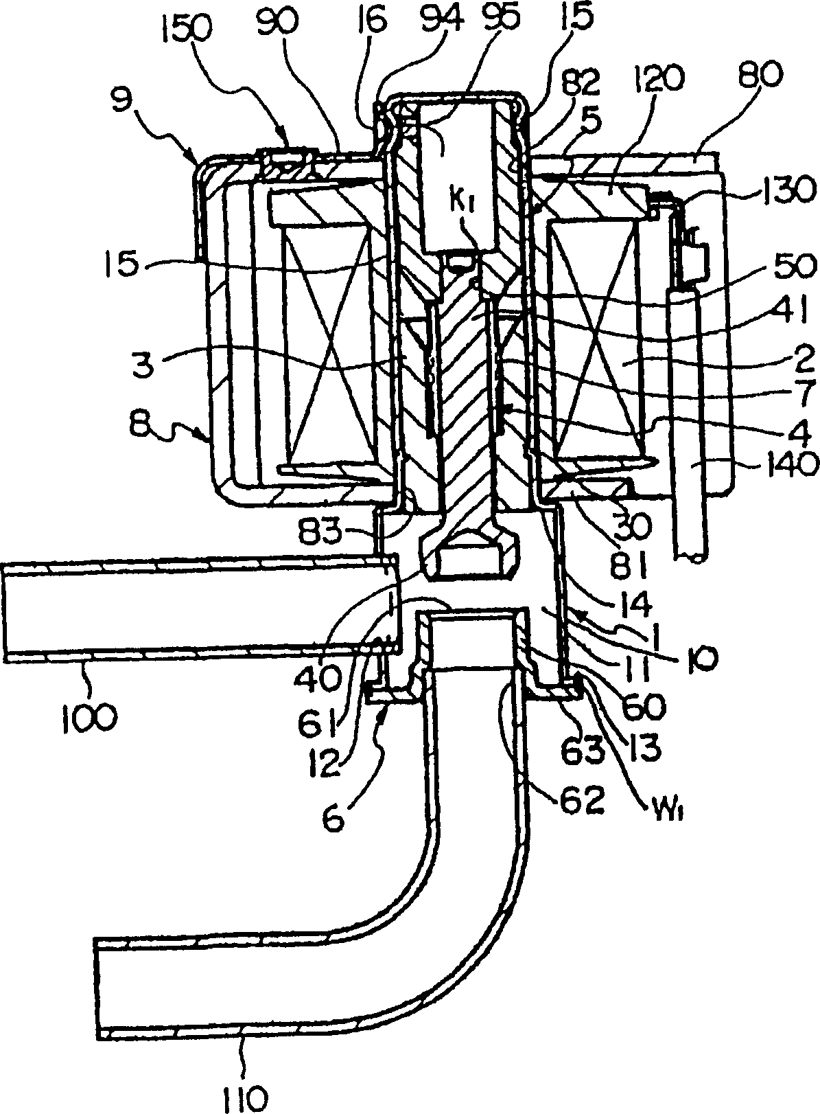
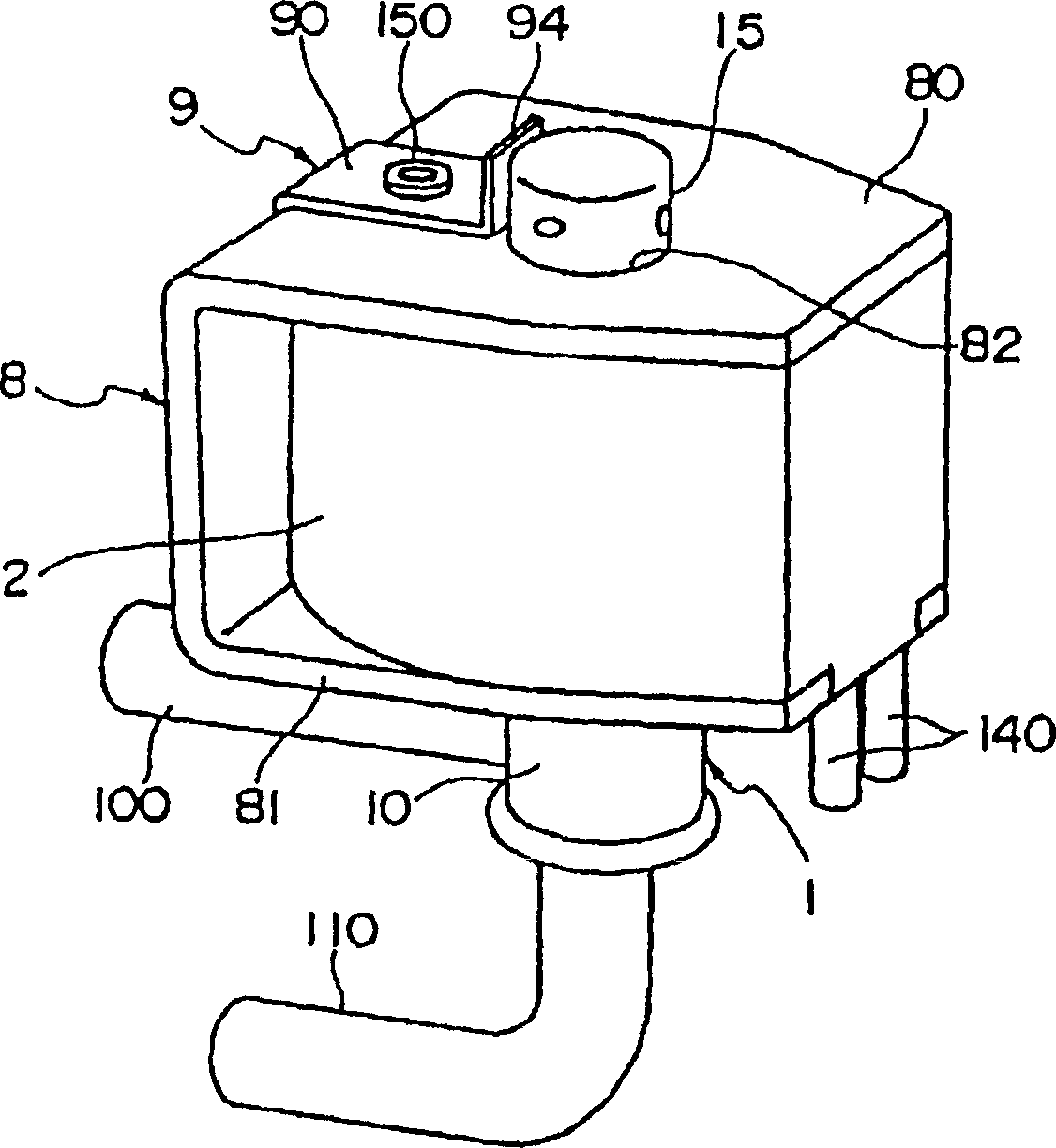
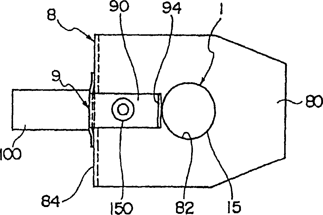
[0033] figure 1 is a longitudinal sectional view showing the solenoid valve in the first embodiment of the present invention, figure 2 is a perspective view showing the solenoid valve in the first embodiment of the present invention, image 3 yes figure 2 floor plan; Figure 4 yes figure 1 Enlarged view of the main part.

[0034] Such as figure 1 As shown, the solenoid valve of the first embodiment has not only the valve chamber 11 but also: a valve body 1 with a pipe portion that blocks one end of the pipe portion 15, an electromagnetic coil 2 disposed on the outer periphery of the pipe portion 15 of the valve body 1, The suction body 3 fixed inside the pipe portion 15 of the valve body 1, the rod-shaped valve body 4 that is arranged on the suction body 3 and can slide freely in the longitudinal direction of the pipe portion 15 of the valve body 1, the plunger 5 connected to the valve body 4, and the The valve seat part 6 with the opening of the main body 1, and the v...

Embodiment 2

[0058] Below, use Figure 5 and Figure 6 A second embodiment of the present invention will be described. The second embodiment involves pair-on-pair Figure 4 The illustrated manner in which the solenoid valve copper tube 100 is bent. Figure 5 It is a longitudinal sectional view of the solenoid valve 163 before processing, Figure 6 It is a longitudinal section view after processing. in addition, Figure 5 and Figure 6 left and right with Figure 4 Left and right are shown in reverse.

[0059] For example, the solenoid valve 163 is configured in the cooling cycle of the air conditioner, such as Figure 6 As shown, opposite to the copper pipe 110 on one side, use the copper pipe 100 on the other side from Figure 5 The straight line shown is often bent (in addition, in figure 1 and figure 2 In the case shown, the copper tube 110 is bent).

[0060] In addition, when the copper pipe 100 is to be bent, in order to save space in the air conditioner, when the copper ...

Embodiment 3

[0074] Refer below Figure 7 to Figure 10 A third embodiment will be described. The third embodiment is with figure 2 and image 3 Different embodiments of the coil housing 8 are shown.

[0075] Figure 7 It is a plan view showing the state that the solenoid valve 163 is installed on the air conditioner indoor unit 161 in the third embodiment of the present invention; Figure 8 It is a function explanatory diagram, (A) shows figure 2 and image 3 The situation of the shown coil housing 8, (B) represents the situation of the solenoid valve 163 in the third embodiment; Figure 9 is a perspective view of the solenoid valve 163 of the third embodiment of the present invention; Figure 10 yes Figure 9 A plan view of solenoid valve 163 is shown. In addition, in Figure 9 to Figure 10 in, with figure 2 and image 3 The same symbols are used for structures having the same constituent parts shown, and their descriptions are omitted.

[0076] Such as Figure 7As shown,...


PUM


Abstract

The present invention can facilitate mobility of fluid in a solenoid valve when opening and shutting the valve by separating and connecting a valve body with respect to a valve seat with magnetic force of a solenoid coil. The solenoid valve is provided with a valve main part 1, the solenoid coil 2, a suctioner 3, the valve body 4, a plunger 5 connecting with the valve body 4, a valve-seat sheet member 6 forming the valve seat 61, and a coil spring 7 arranged between the suctioner 3 and the plunger 5. When electricity is applied to the solenoid coil 2, a magnetic force caused by electric conduction of the solenoid coil 2 is generated on the suctioner 3, and the plunger 5 moves toward the suctioner 3 while resisting to urging force of the coil spring 7. The valve body 4 moves toward the valve seat 61 of the valve-seat sheet member 6 together with the plunger 5, the valve body 4 is firmly touched with the valve seat 61 of the valve-seat sheet member 6, and the solenoid valve performs a closing-valve operation. A clearance 17 is formed between a pipe portion 15 and the suctioner 3, and caulked portions 20 are provided in a plurality of places by caulking so as to maintain the clearance.

Description

technical field [0001] The present invention relates to solenoid valves. The electromagnetic valve uses the magnetic force of the electromagnetic coil to open and close the valve relative to the valve seat and the valve body. Background technique [0002] In the prior art, Japanese Patent Application Laid-Open No. 2001-108136 discloses a solenoid valve that closes when energized. It is provided with a solenoid coil around the plunger tube arranged on the valve body, and the valve body in the plunger tube A movable suction body is provided on one side, and a plunger is provided on the other side. When the movable suction body and the plunger are driven by an opening and closing spring, the plunger and the valve body are retracted and released by riveting. [0003] However, in the conventional Japanese Patent Application Laid-Open No. 2001-108136, the solenoid valve that is closed when energized not only uses brass as the material of the valve body, but also increases the wei...

Claims


Application Information

Patent Timeline
Patent Type & Authority Applications(China)
IPC IPC(8): F16K31/06F16K1/00
Inventor 今井正幸木船仁志
Owner FUJIKOKI MFG CO LTD
Learn More