Optical fibre collimator and making method thereof
A technology of optical fiber collimator and manufacturing method, which is applied in the field of collimator and can solve the problems of large volume and the like
- Summary
- Abstract
- Description
- Claims
- Application Information
AI Technical Summary
Problems solved by technology
Method used
Image

Examples
Embodiment 1
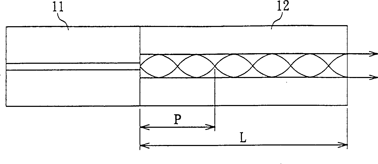
[0020] Please refer to figure 1 According to a preferred embodiment of the present invention, the fiber collimator 1 includes: a single-mode fiber (single-mode fiber) 11 and a graded-index multi-mode fiber (graded-index multi-mode fiber) 12 . In the single-mode fiber 11, the light travels by total reflection. Since in the graded-index multimode fiber 12 , the change of the refractive index will continuously change direction toward the fiber axis, so in the graded-index multimode fiber 12 , the light will propagate in a waveform with a period P.
[0021] In this embodiment, the relationship between the length L of the graded-index multimode fiber 12 and the period P is:
[0022] L=0.25×N×P
[0023] Where N is a positive odd number. If the length L and the period P conform to the above relationship, the light will be emitted in the form of parallel light after passing through the graded-index multimode fiber 12 . In addition, the graded-index multimode fiber 12 and th...
Embodiment 2
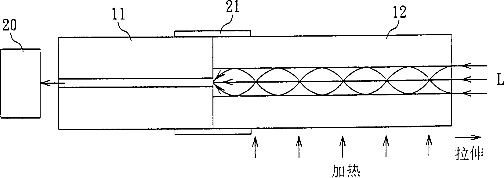
[0028] Please refer to Figure 3A and Figure 3B , In another embodiment of the present invention, the graded-index multimode fiber 12 is fused with the single-mode fiber 11 first, and then the end face of the graded-index multimode fiber 12 is polished and smoothed. Next, the light beam B is coupled into the single-mode fiber 11 , and at the same time, an optical scanner 30 (beam scanner) is used to monitor the tangential size of the output light from the graded-index multimode fiber 12 .
[0029] At this time, the graded-index multimode fiber 12 is heated, and the graded-index multimode fiber 12 is slowly stretched to change its length. During stretching, by monitoring the size of the optical section detected by the optical scanner 30 , it can be known whether the light output from the graded-index multimode fiber 12 is substantially parallel light. If the output result of the optical scanner 30 shows that the output light from the graded index multimode fiber 12 is substa...
Embodiment 3
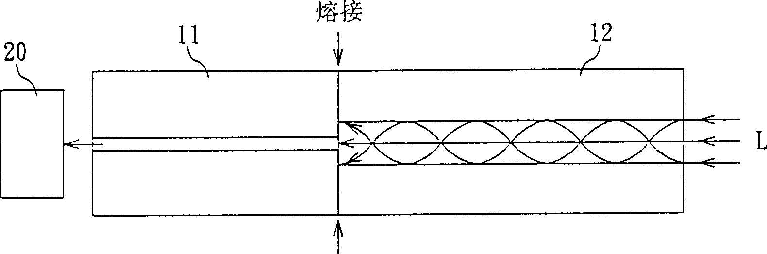
[0031] Please refer to Figure 4 , in another embodiment of the present invention, the length of the graded-index multimode fiber 12 has been calculated in advance, and is approximately equal to 0.25×N×P, where N is a positive odd number, and P is the length of the light passing through the graded-index multimode fiber. 12 cycles of the marching waveform. One end of the single-mode fiber 11 is polished, and the other end is coupled with a light source, so that the light beam B enters the single-mode fiber 11 .
[0032] Next, the relative positions of the single-mode fiber 11 and the graded-index multimode fiber 12 are adjusted, and the optical scanner 30 is used to monitor the size of the cross section of the light output by the graded-index multimode fiber 12 . When the output result of the optical scanner 30 shows that the output light from the graded-index multimode fiber 12 is substantially parallel light, a fixing glue is added to the connection between the single-mode f...
PUM
 Abstract
Description
Claims
Application Information
 - R&D Engineer
- R&D Manager
- IP Professional
- Industry Leading Data Capabilities
- Powerful AI technology
- Patent DNA Extraction
Browse by: Latest US Patents, China's latest patents, Technical Efficacy Thesaurus, Application Domain, Technology Topic.
© 2024 PatSnap. All rights reserved.Legal|Privacy policy|Modern Slavery Act Transparency Statement|Sitemap