Gas shock-wave generating device

A generating device and shock wave technology, applied in the direction of solid residue removal, combustion product treatment, combustion method, etc., can solve the problems of short time, difficult to achieve door opening effect, difficult to produce usable strength, etc.

Inactive Publication Date: 2003-08-27
成都波倍科技有限公司
View PDF0 Cites 10 Cited by
  • Summary
  • Abstract
  • Description
  • Claims
  • Application Information

AI Technical Summary

Problems solved by technology

Among the three methods, the detonation combustion method has been practically applied in some fields, such as the soot blowing on the low-temperature heating surface of the boiler, and the gas cannon specially used for bombing birds in the airport to ensure the safety of aircraft take-off and landing. Since it uses combustible gas, There are safety problems in the use and maintenance of equipment. For example, although the effect of soot blowing on the heating surface of the boiler is obvious, it can only be used for soot blowing on the heating surface at the tail of the boiler where the flue gas temperature is low, and it is difficult to apply in the high temperature section.
The membrane rupture method is limited to shock tube experiments in aerodynamic

Method used


Image

  • Gas shock-wave generating device
  • Gas shock-wave generating device
  • Gas shock-wave generating device

Examples


Embodiment 1

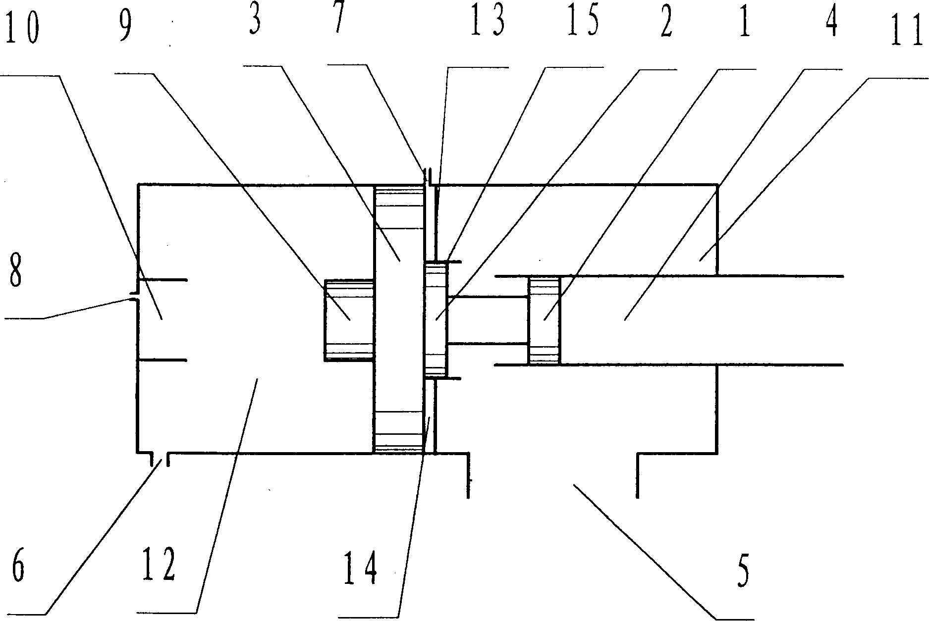
[0019] Example 1: figure 1 Among them, piston 1, piston 2, and piston 3 form a sealed piston group with different sealing cross-sectional areas, piston 1 separates the gas between the sealed energy storage chamber 11 and the shock tube 4, and piston 2 separates the sealed rear chamber 14 from the To seal the gas between the energy storage chambers 11, the sealing cross-sectional area of ​​the piston 2 refers to the sealing cross-sectional area of ​​the piston 2 to the side of the energy storage chamber 11, and the piston 3 separates the gas between the sealed front chamber 12 and the sealed rear chamber 14, and its Corresponding sealing section diameters are D 1 、D 2 、D 3 , the middle partition 13 and the piston 3 divide the device into three chambers: the sealed front chamber 12, the sealed rear chamber 14, and the sealed energy storage chamber 11, D 3 >D 2 ,D 3 -D 2 Take big, D 2 >D 1 ,D 2 -D 1 Take very small. figure 1 The working process shown in can be divided ...

Embodiment 2

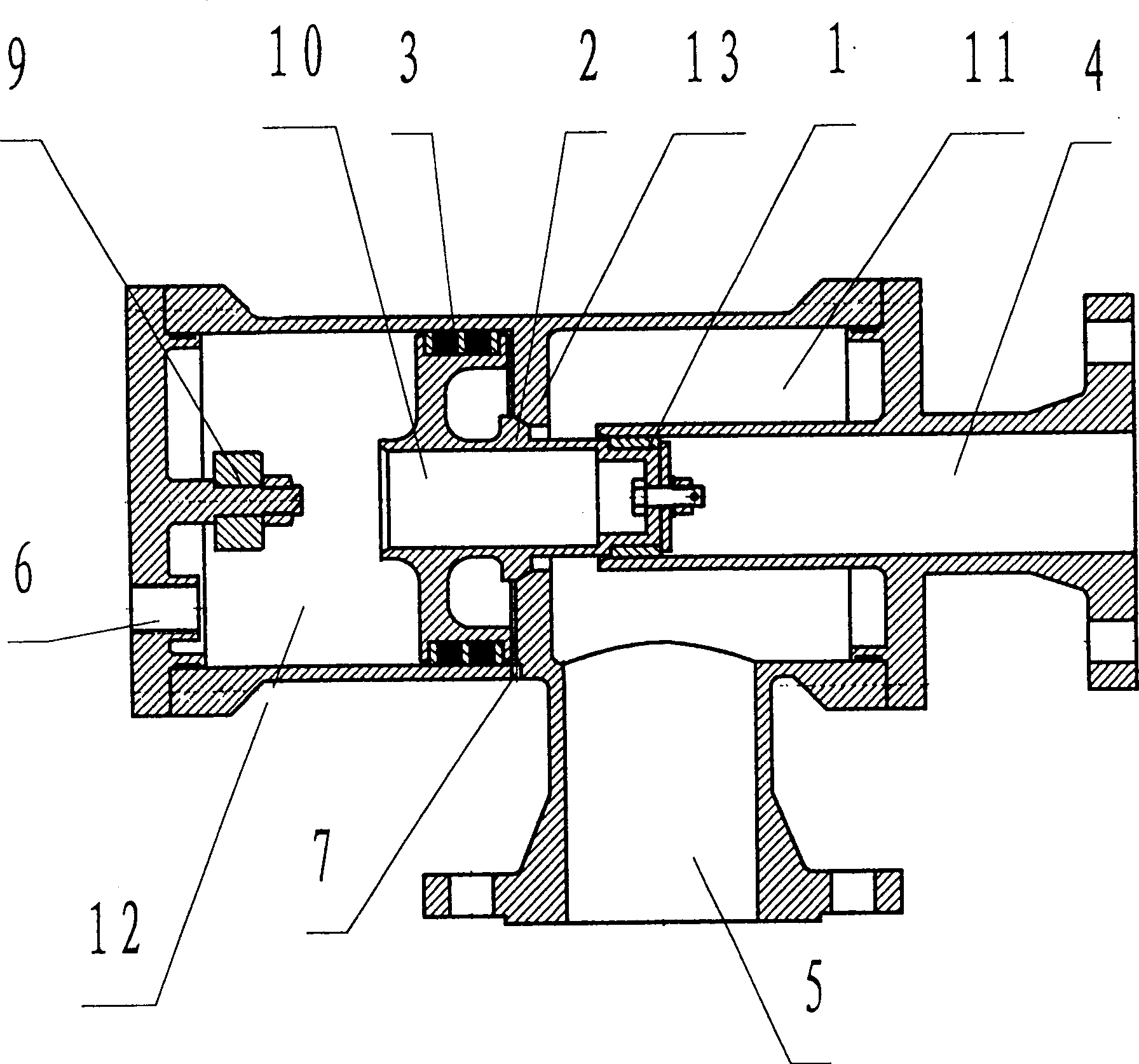
[0027] Example 2: figure 2 In the shown embodiment, the piston 1, the piston 2, the piston 3 and the buffer chamber 10 form a whole, there is no connecting member between the pistons, and the external gas storage tank is partially communicated with the sealed energy storage chamber 11 through the large-diameter air inlet 5, connect. When the piston group impacts at a high speed, after the piston 1 opens the door for a certain distance, the buffer plunger 9 enters the buffer chamber 10, and the buffer plunger 9 is provided with a buffer orifice with a small diameter. After the piston group is buffered for a certain distance, the impact stops.

Embodiment 3

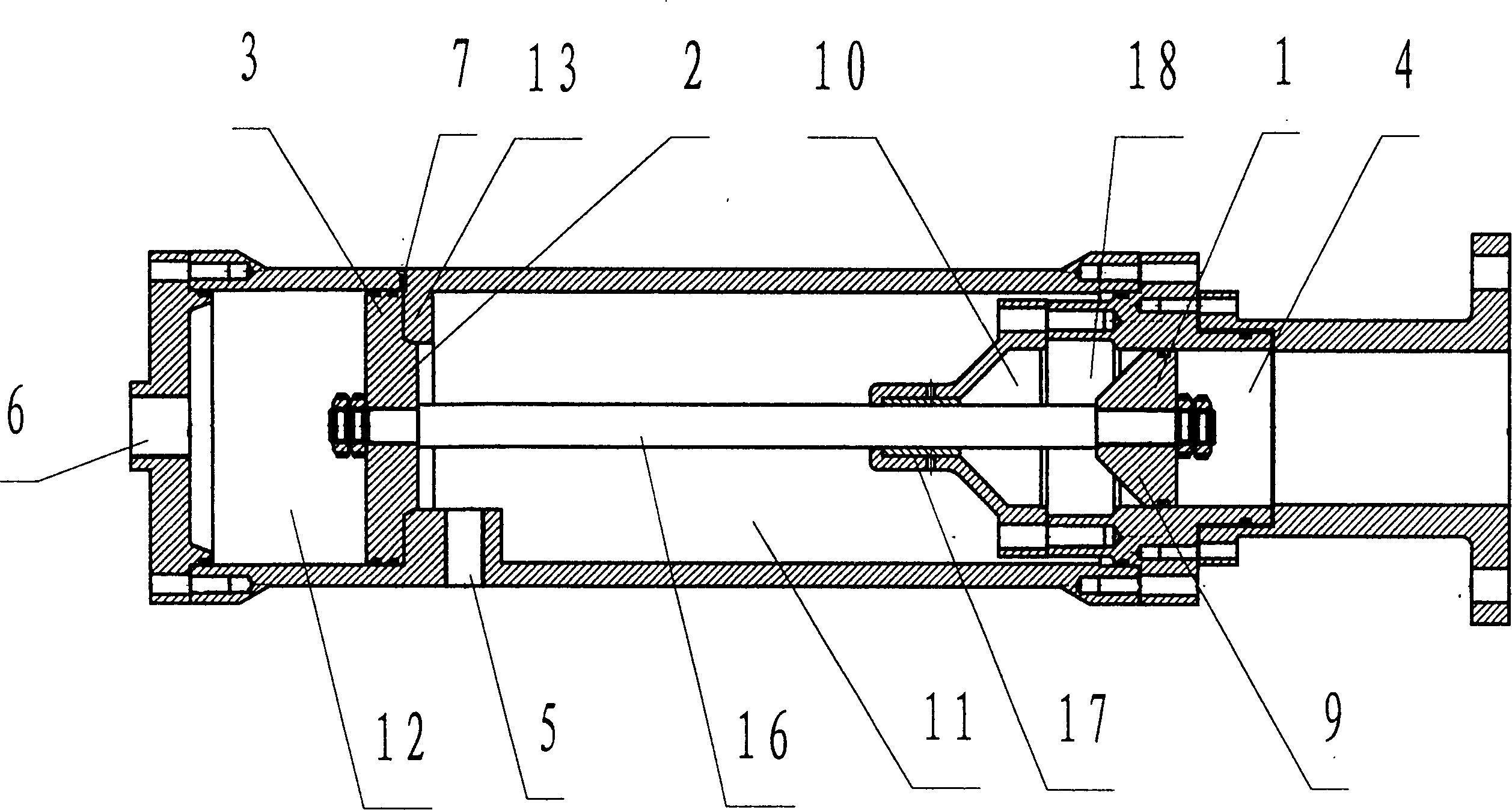
[0028] Example 3: image 3 In the shown embodiment, the gas storage tank and the energy storage chamber 11 are integrated, the piston 2, the piston 3 and the piston 1 are connected through the piston rod 16, and the buffer chamber 10 is placed in the sealed energy storage chamber 11 and connected to the piston rod shaft 17 Connected as a whole, the circumferential inlet slot 18 is between the buffer chamber 10 and the shock tube 4 .


PUM


Abstract

The invention discloses a kind of gas blast generating device, it includes holistic valve group, seal cavity, seal energy storing cavity, blast tube, and middle separating board. The valves have unequal seal cross-section area, one valve moving in the seal cavity, the middle separating board separates the seal cavity and the seal energy storing cavity, one of the valves can move along the blast tube, the blast tube is at one end of the seal energy storing cavity and connects with the cavity.

Description

Technical field: [0001] The invention relates to a gas shock wave generating device, in particular to a gas shock wave generating device suitable for a boiler soot blower, a gas dynamic shock wave tube and a large-energy air cannon. Background technique: [0002] In the existing technology, the methods for artificially generating plane shock waves in the tube include: the detonation combustion method, in which the combustible gas and the combustion-supporting gas are mixed and detonated to burn through the impact tube; The diaphragm is used to break the membrane instantly and the high-pressure gas is suddenly contacted with the low-pressure gas, and then it is generated in the low-pressure gas section tube along the blasting impact direction; the piston method, the piston in the tube suddenly accelerates forward and is generated in the tube in front of the piston movement direction. Among the three methods, the detonation combustion method has been practically applied in som...

Claims


Application Information

Patent Timeline
IPC IPC(8): F23J1/00F23J3/00
Inventor 董勇强
Owner 成都波倍科技有限公司
Why Eureka
Try Eureka