Check patentability & draft patents in minutes with Patsnap Eureka AI!

Electromagnetic field sensors

An electric field sensor and sensor probe technology, applied in electromagnetic field characteristics, instruments, measurement of electrical variables, etc., can solve problems such as low detection sensitivity, easy damage to electrodes, and difficulty in detecting strong electric fields.

Inactive Publication Date: 2003-09-03
TOKIN CORP
View PDF0 Cites 3 Cited by
  • Summary
  • Abstract
  • Description
  • Claims
  • Application Information

AI Technical Summary

Problems solved by technology

[0005] However, in the prior electric field sensor of this kind, when a strong electric field is detected, the discharge of the electric charge induced by the voltage applied to the two electrodes whose distance is only a few μm to tens of μm is easy to damage the electrodes, so it is difficult to apply Detecting strong electric fields
[0006] In addition, in the prior electric field sensor of this kind, the electrode capacitance related to the electrode length is usually very large, so the detection sensitivity is not too high.

Method used


Image

  • Electromagnetic field sensors
  • Electromagnetic field sensors
  • Electromagnetic field sensors

Examples


Embodiment 1

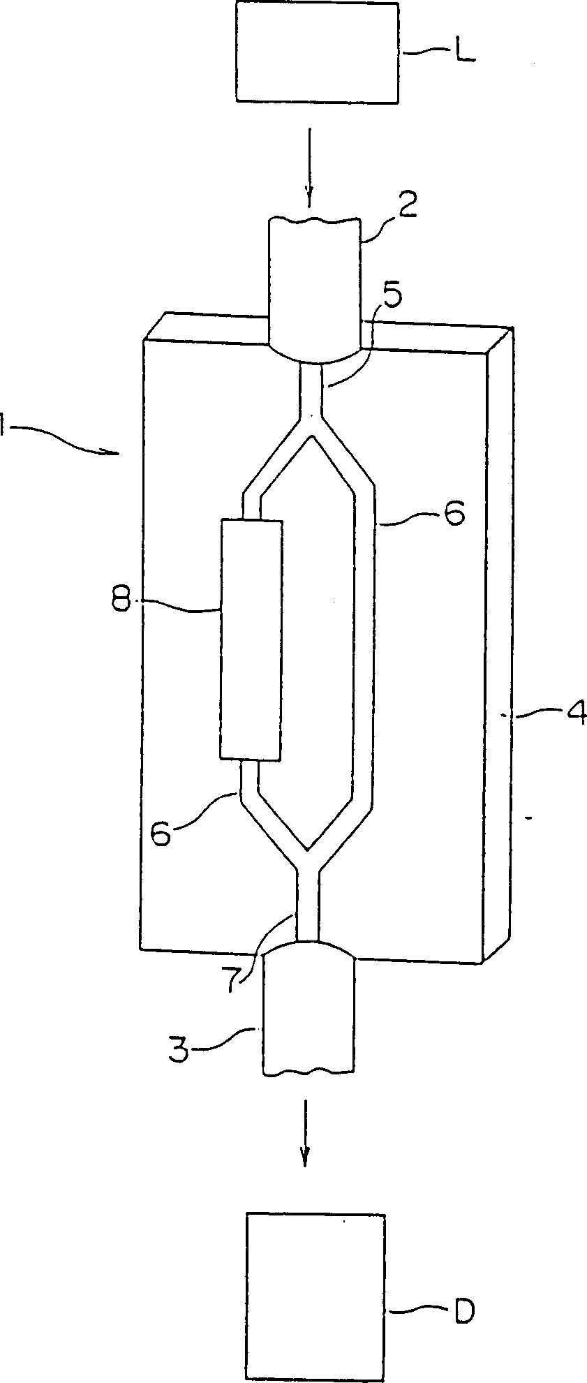
[0023] Such as image 3 As shown, the electric field sensor of the present invention has a sensor probe 1 , an incident optical fiber 2 and an outgoing optical fiber 3 , a light source L and a light detector D.

[0024] The aforementioned sensor probe 1 is configured such that the intensity of transmitted light varies with the intensity of an applied electric field. The incident optical fiber 2 and the outgoing optical fiber 3 are connected to the sensor probe 1 . The above-mentioned light source L is constituted by a semiconductor laser or the like. The light source L is coupled to one end of the incident fiber 2 to irradiate the incident fiber 2 with light. The photodetector D detects the transmitted light emitted from the outgoing optical fiber 3 through the sensor probe 1 .

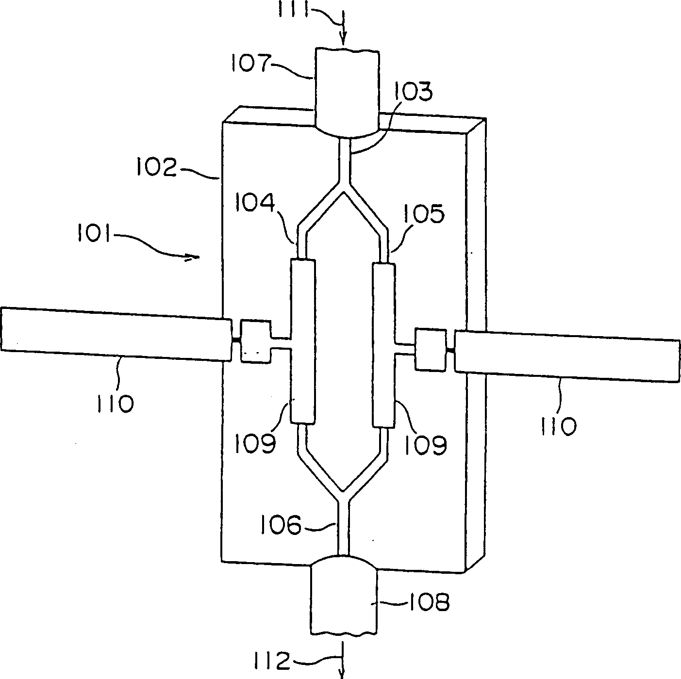
[0025] The sensor probe 1 described above has a substrate 4 , an incident optical waveguide 5 , two branch optical waveguides 6 , an outgoing optical waveguide 7 , and an electric field shielding m...


PUM


Abstract

An electric field sensor comprises a substrate 4, an incident optical waveguide 5 formed on the substrate 4, two branched optical waveguides 6 formed on the substrate 4 to be branched from the incident optical waveguide 5 and having refractive indexes which are variable in response to an electric field intensity applied thereto, an outgoing optical waveguide 7 formed on the substrate 4 to join the branched optical waveguides 6, and an electric field shielding member 8 formed in the vicinity of a part of the branched optical waveguides 6 for shielding an electric field. The substrate 4 may be provided with a reflection mirror 16 for reflecting light beams from the branched optical waveguides 6. The substrate 4 is made of a ferroelectric material and has polarization directions reverse to each other at portions where the two branched optical waveguides 6 are formed.

Description

technical field [0001] The invention relates to an electric field sensor for measuring batteries and electromagnetic noise, in particular to an electric field sensor for measuring the electric field intensity of electromagnetic waves propagating in space. Background technique: [0002] figure 1 This is an example of the structure of the conventional electric field sensor probe 101 made of a waveguide element. The electric field sensor probe 101 has a substrate 102 of lithium niobate crystal cut perpendicular to the C-axis, an incident optical waveguide 103 formed after diffusion of titanium on the substrate 102, and phase shift optical waveguides 104, 105 branched from the incident optical waveguide 103 The output optical waveguide 106 is combined with these phase-shifted optical waveguides 104 and 105. The incident end of the incident optical waveguide 103 is connected to the incident optical fiber 107 , and the outgoing end of the outgoing optical waveguide 106 is connec...

Claims


Application Information

Patent Timeline
Patent Type & Authority Applications(China)
IPC IPC(8): G01R15/24G01R29/08
CPCG01R29/0885G01R15/241G01R15/00
Inventor 户叶祐一近藤充和
Owner TOKIN CORP
Features
  • R&D
  • Intellectual Property
  • Life Sciences
  • Materials
  • Tech Scout
  • Unparalleled Data Quality
  • Higher Quality Content
  • 60% Fewer Hallucinations
Learn More