Image treatment equipment and ultrasonic diagnosis equipment

An image processing device and image data technology, applied in image data processing, image data processing, acoustic wave diagnosis, etc., can solve the problems of expensive MRI, difficult tracking, expensive equipment, etc.

Inactive Publication Date: 2003-09-17
TOSHIBA MEDICAL SYST CORP
View PDF0 Cites 28 Cited by
  • Summary
  • Abstract
  • Description
  • Claims
  • Application Information

AI Technical Summary

Problems solved by technology

However, there is a problem that MRI is a very expensive device, and at the same time, image acquisition cannot be performed by markers in real time
[0012] On the other hand, when the tissue Doppler method is employed, there is a problem that the equipment is expensive due to the need for a cross-correlation calculation circuit for Doppler calculation.
Also, not easy to track in other directions

Method used


Image

  • Image treatment equipment and ultrasonic diagnosis equipment
  • Image treatment equipment and ultrasonic diagnosis equipment
  • Image treatment equipment and ultrasonic diagnosis equipment

Examples


no. 1 example

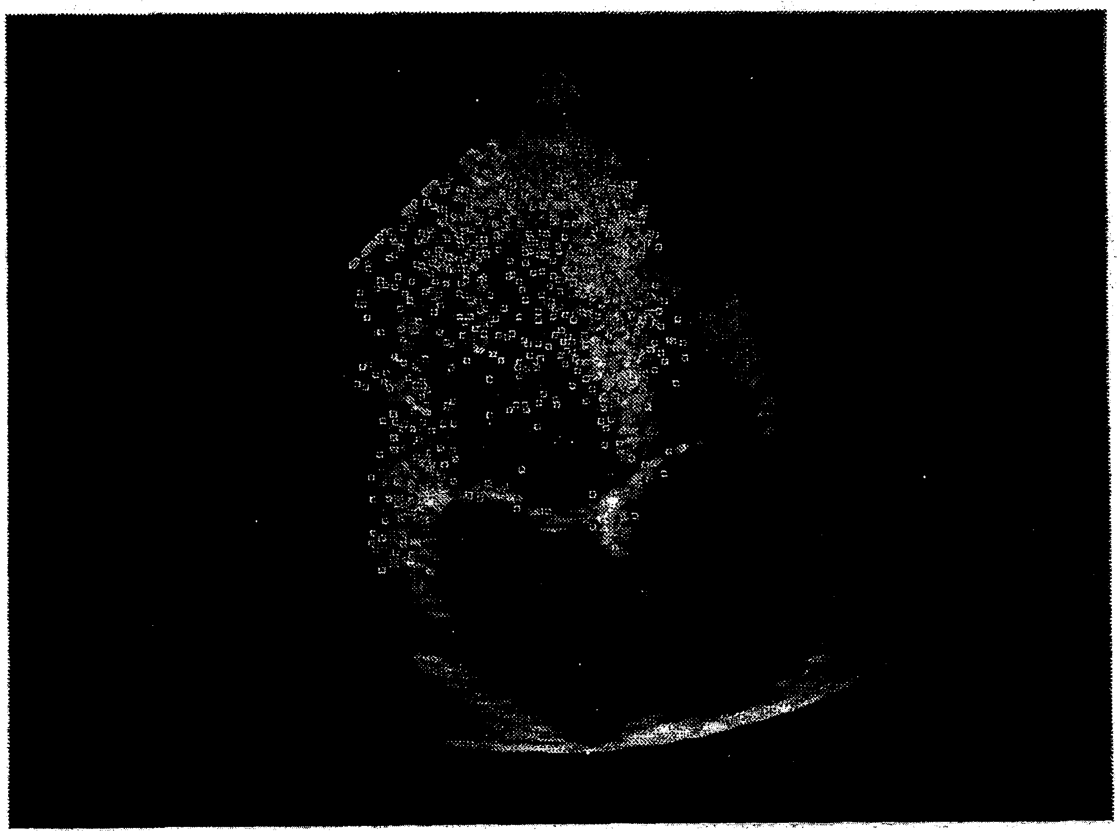
[0045] First, the advantages of the invention should be pointed out. The advantage of the present invention is that some feature points that can be tracked can be automatically extracted and displayed on the ultrasonic image at the same time, so that the feature points can be easily selected.

[0046] In addition, the accuracy of the estimated value is improved by increasing the movement amount of any point (grid point) obtained by estimating the typical value of multiple tracking points after tracking is realized. In addition, this system has low-cost, high-time-resolution ultrasonic diagnostic equipment, in which the feature points are associated with the grid points, so it is easy to realize the calculation of deformation, etc., can be observed through perception, and can be obtained through marking Information about heart function.

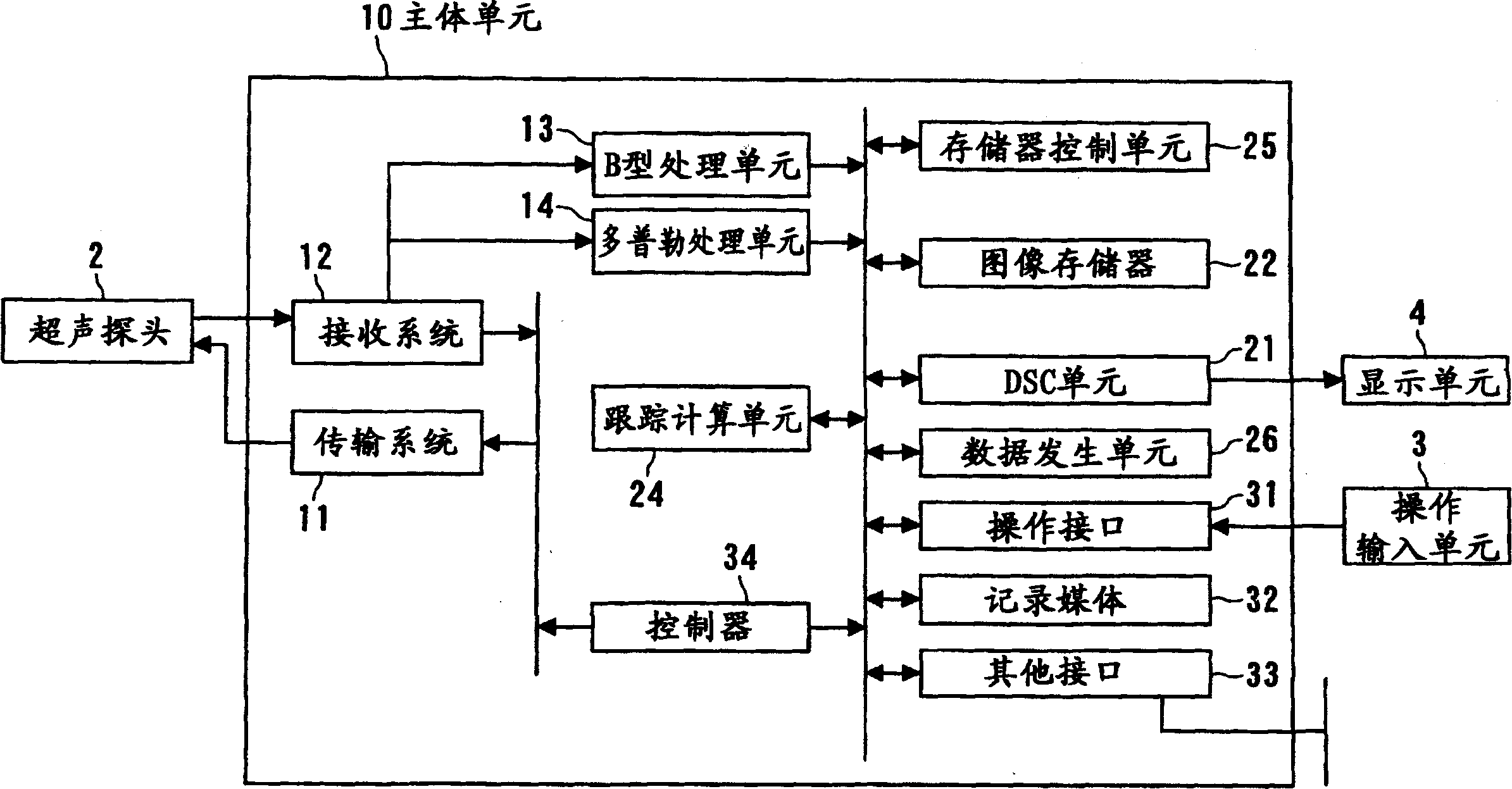
[0047] Refer below figure 1 The features described above and the overall schematic structure of the ultrasonic diagnostic equipment hardwar...

no. 3 example

[0183] Refer below Figure 8 to Figure 1 0 to describe the third embodiment of the present invention. It should be noted that the description of the structure basically the same as that of the above-mentioned first embodiment is omitted, and only the different parts are described. Figure 11 To show an exemplary structure of the ultrasonic diagnostic apparatus of this embodiment.

[0184] According to this embodiment, for example, the papillary muscle, the annulus, and any representative site in the myocardium can be tracked, and clinically important cardiac microstructure information can be provided according to the tracking results.

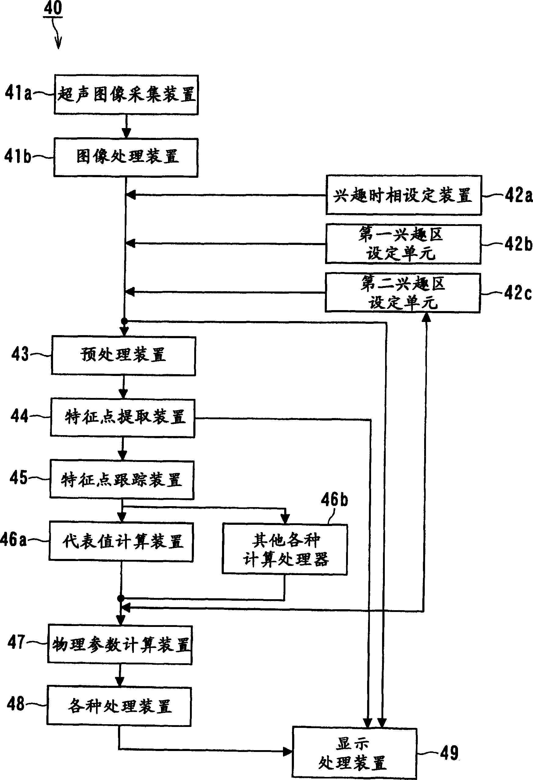
[0185] Specifically, the software module 100 of the ultrasonic diagnostic equipment of the present embodiment includes these structures that are substantially the same as those in the first embodiment: an ultrasonic image acquisition device 101a, a phase of interest setting device 102a, an image processing device 101b, a preprocessing device ...

no. 4 example

[0202] Refer below Figure 14 A fourth embodiment of the present invention will be described. Figure 14 is a functional block diagram showing the fourth embodiment of the present invention.

[0203] Each of the embodiments described above has been described with respect to ultrasonic diagnostic apparatuses that display ordinary two-dimensional images, but in recent years, ultrasonic diagnostic apparatuses that can obtain three-dimensional images have appeared. In this case, a design is made in which a two-dimensional image is formed by taking an arbitrary section from a three-dimensional image, and the above-described embodiments are employed. In addition, a design has been made in which a three-dimensional region of interest is formed within a grid pattern for voxel data and three-dimensional tracking is performed so that various three-dimensional physical parameters can be calculated and displayed.

[0204] Specifically, as Figure 14 As shown, the software module struct...


PUM


Abstract

The present invention relates to an ultrasonic imaging device and an ultrasonic diagnostic device including an image processing unit. The image processing device includes: an image acquisition unit, an extraction unit, a tracking unit and a physical parameter calculation unit. The image acquisition unit is used to collect the image data of the measured object; the extraction unit extracts a plurality of trackable feature points according to the collected image data; the tracking unit tracks the movement of the feature points; information to obtain the specific physical parameters of the feature points located in each ROI. The specific physical parameters are, for example, displacement, deformation and deformation speed. The ultrasonic imaging device and ultrasonic diagnostic device can more easily and accurately extract feature points, and perform low-cost analysis on systolic / diastolic functions such as the heart.

Description

technical field [0001] The present invention relates to image processing equipment and ultrasonic diagnostic equipment, and more particularly, to such ultrasonic diagnostic equipment in which the movement of feature points (labels) obtained from organ images is tracked, and based on the above-mentioned tracking of label movement Evaluate and output information related to various local functions of tissues, thereby providing useful clinical information. Background technique [0002] Quantitative evaluation of local motion (systolic / diastolic function) such as the heart is a very important matter for understanding the heart function. It is known, for example in the case of ischemic heart disease, that changes in the local heart wall motion occur due to coronary insufficiency. [0003] Many traditional methods have been proposed for the quantitative assessment of regional heart wall motion. These examples include "MRI marker (magnetic marker) method", "two-dimensional motion ...

Claims


Application Information

Patent Timeline
Patent Type & Authority Applications(China)
IPC IPC(8): A61B8/14G06T1/00G06T5/00G06T7/20G06T7/60
CPCA61B8/0883A61B8/14G06T2207/10136G06T2207/20132G06T2207/30048G06T7/12G06T7/246
Inventor 辻野弘行西浦正英
Owner TOSHIBA MEDICAL SYST CORP
Why Eureka
Try Eureka