
Preloaded parabolic dish antenna and method of making it

A technology of reflector antenna and parabolic cylinder, which is applied in the direction of antenna, wind load reduction, electrical components, etc., and can solve problems such as labor consumption, increased weight of structural components, and complexity

Inactive Publication Date: 2003-09-24
塔塔基础研究院
View PDF8 Cites 10 Cited by
  • Summary
  • Abstract
  • Description
  • Claims
  • Application Information

AI Technical Summary

Problems solved by technology

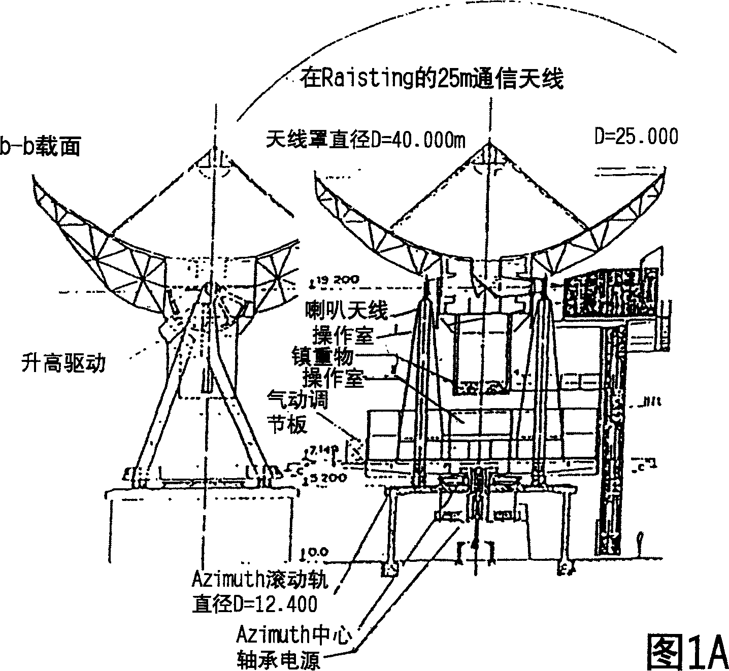
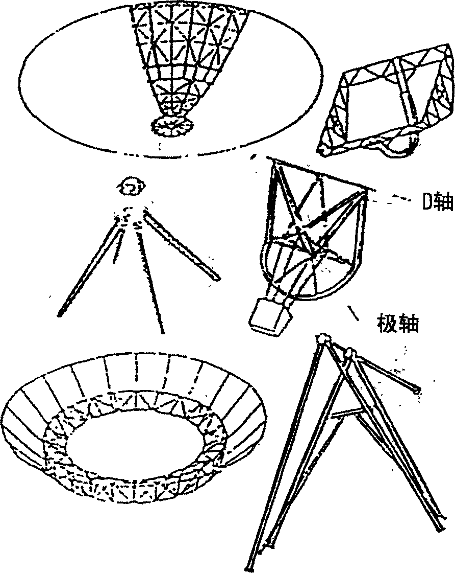
[0038] As can be seen from Figure 1, the conventional design of the support structure for parabolic reflector antennas described in the literature becomes complicated for large diameter parabolic reflectors
Traditional designs add weight to structural components and also require extensive welding or stud connections
Moreover, the required curvature of the radial circumference is all produced by rolling or bending in suitable machines, which is labor-intensive

Method used


Image

  • Preloaded parabolic dish antenna and method of making it
  • Preloaded parabolic dish antenna and method of making it
  • Preloaded parabolic dish antenna and method of making it

Examples


Embodiment Construction

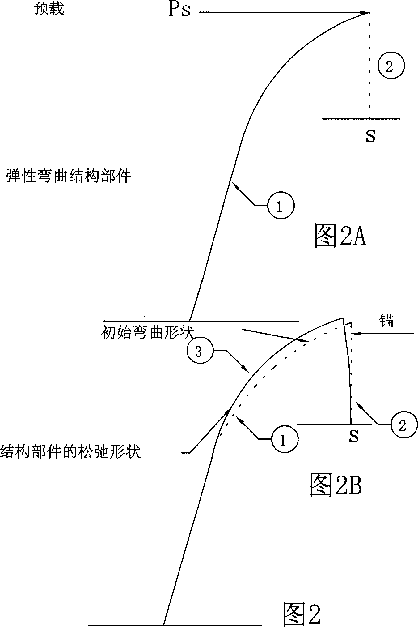
[0091] The curvature of the radial elements requiring elastic bending can be made to approximate the same as the parabolic curvature of the parabolic antenna in many ways, for example, (a) by fixing the straight radial elements at the appropriate location at the central hub and at an angle of inclination relative to the central hub , then the normal component exerts force at their tips to achieve the desired curvature, and then rigidly connects them to the rim parts forming an approximately circular (regular polygonal) circumferential ring; (b) first, the radial parts are lightly Gently bend to a relatively large radius of curvature, then fix them at the appropriate inclination angle and position of the central hub, and then apply force at their tips with the normal component used to achieve the desired curvature; (c) first use the appropriate The tensioning means elastically bends the radial members from the hub to the intermediate ring formed by the bracing members and from t...


PUM


Abstract

The parabolic reflector antenna, by preloading its radially circumferentially placed straight support members to support its reflective surface, makes it significantly lighter and also plays a role in its installation. The support structure for the preloaded parabolic reflector antenna consists of a central hub, an assembly of an appropriate number of resiliently curved radial structural members, an equal number of straight structural members connected to the tips of the radial members at the outer rim of the parabolic antenna, and circumferentially located The straight brace components in the middle position are all tensioned to the specified prestress value when there is no wind load. The outermost rim part located at the periphery of the parabolic antenna forms the opening of the parabolic antenna. Fixing the radial part at an appropriate inclination angle and position at the hub, applying a force with a normal component at its tip to elastically bend the radial part with a curvature approximately the same as the parabolic curvature between the hub and the peripheral rim point, so that the supporting member Has a parabolic shape.

Description

technical field [0001] The invention relates to a parabolic reflector antenna used in microwave communication, and also relates to a manufacturing method of the parabolic reflector antenna. In particular, the invention relates to parabolic reflector antennas having a diameter in the range of about 5m to 100m. Background technique [0002] Parabolic reflectors are also used in UHF and microwave communications, satellite communications, troposcatter communications, radar and similar applications for receiving and / or transmitting radio signals. [0003] Parabolic reflector antennas consist of a metal or metallized parabolic reflective surface supported by support members. Radio waves from distant radio sources or radio transmitters are reflected by the parabolic reflector surface and converge at the focal point of the parabolic antenna, where the radio waves are received by the main antenna feed and amplifier unit. Similar to transmitting antennas, radio waves from the transm...

Claims


Application Information

Patent Timeline
Patent Type & Authority Applications(China)
IPC IPC(8): H01Q15/14H01Q15/16
CPCH01Q1/005H01Q15/141H01Q15/147H01Q15/168
Inventor 戈文德·斯瓦鲁普苏雷什·钱德拉·塔德
Owner 塔塔基础研究院
Learn More