
Mfg. method of thrust plate and mfg. method of shaft for fluid power bearing

A manufacturing method and thrust plate technology, which are applied in the directions of shafts and bearings, sliding contact bearings, manufacturing of motor generators, etc., can solve the problems of product height variation and insufficient elimination, and achieve the effect of improving bearing performance.

Inactive Publication Date: 2003-10-08
株式会社长野早出 +1
View PDF2 Cites 7 Cited by
  • Summary
  • Abstract
  • Description
  • Claims
  • Application Information

AI Technical Summary

Problems solved by technology

Furthermore, this undulation is not sufficiently eliminated during the pressing step, resulting in variations in the height of the product

Method used


Image

  • Mfg. method of thrust plate and mfg. method of shaft for fluid power bearing
  • Mfg. method of thrust plate and mfg. method of shaft for fluid power bearing
  • Mfg. method of thrust plate and mfg. method of shaft for fluid power bearing

Examples


no. 1 example

[0040] a. The overall structure of the spindle motor

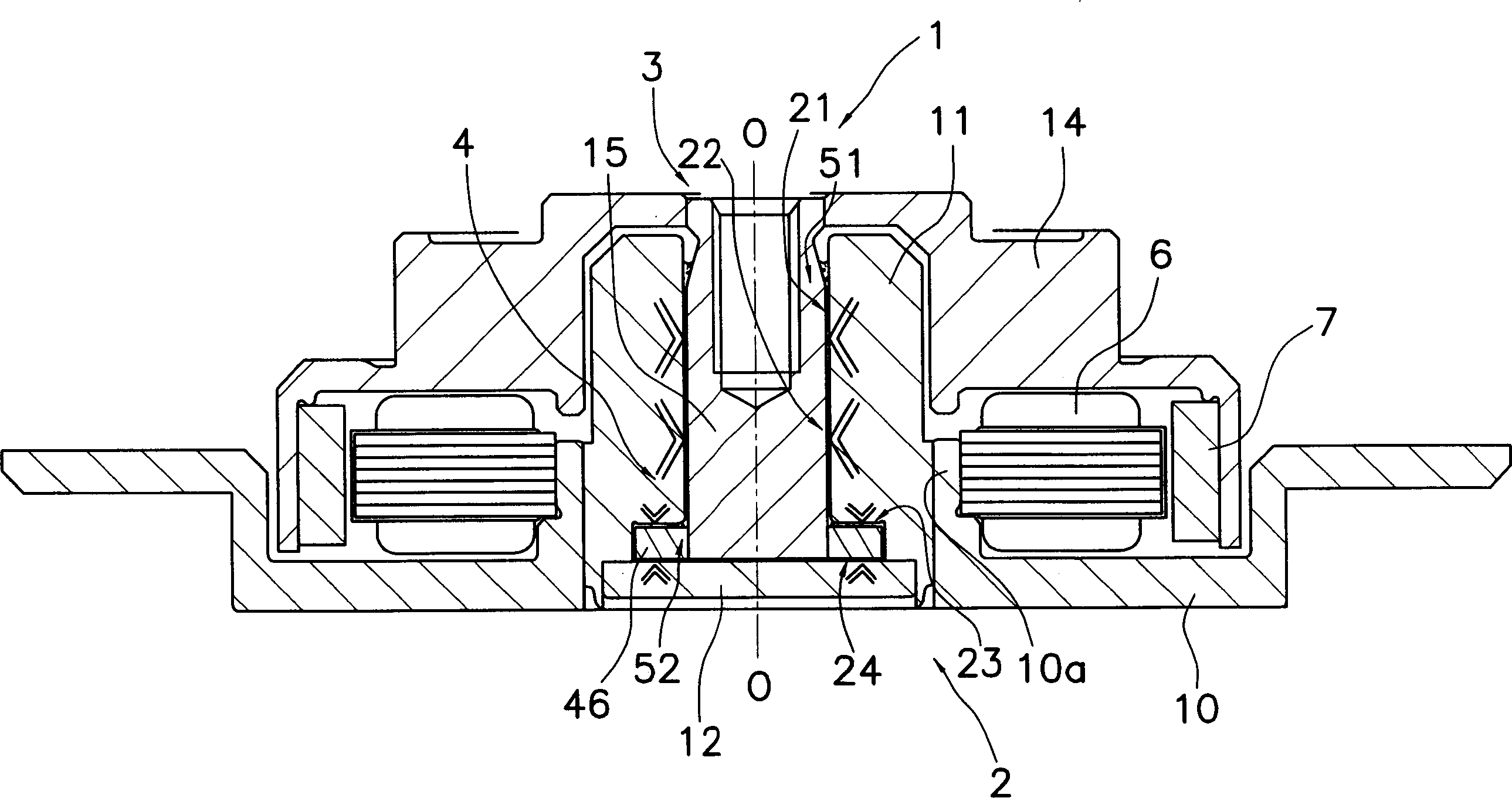
[0041] figure 1 is a longitudinal sectional view showing a simplified structure of a spindle motor according to an embodiment of the present invention. The spindle motor 1 is a spindle motor for recording disk drive, and constitutes an integral part of a recording disk drive device such as a hard disk or the like.

[0042] It should be pointed out that figure 1 The middle O-O line is the axis of rotation of the spindle 1. In addition, although in this embodiment for the sake of brevity the figure 1 The vertical direction in is described as the axis vertical direction, but the actual position where the spindle motor 1 is installed is not limited thereto.

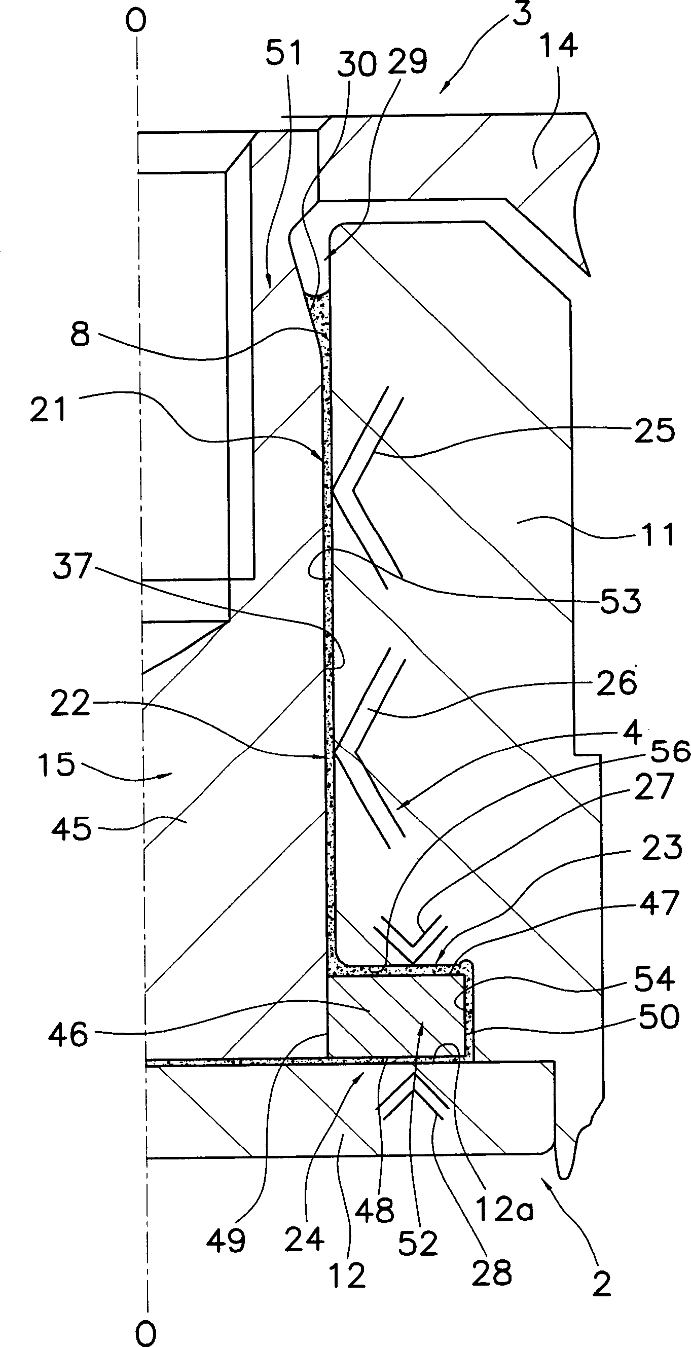
[0043] exist figure 1 Among them, the main shaft 1 mainly includes a stationary part 2, a rotating part 3 and a bearing mechanism 4, and the bearing mechanism 4 is used to support the rotating part 3 on the stationary part 2, so that the rotating part 3 can freely ro...


PUM

PropertyMeasurementUnit
thicknessaaaaaaaaaa

Abstract

A method of manufacturing a thrust plate for a dynamic pressure bearing, the upper and lower end surfaces of the thrust plate have a high-precision vertical angle with respect to its center hole. The thrust plate is circular, and a central hole for the shaft assembly is formed therein. Thrust surfaces constituting a part of the thrust bearing are formed on both end surfaces of the thrust plate. The manufacturing method of the thrust plate comprises the steps of: a blanking step of press-cutting a disc-shaped workpiece to obtain a circular blank semi-finished product, an end face polishing step of polishing both end faces of said blank semi-finished product, and simultaneously press-cutting the inner hole of the polished blank semi-finished product and the outer circumference in order to scrape off its surface scraping step.

Description

technical field [0001] The present invention generally relates to a method of manufacturing a thrust plate for a shaft in a dynamic pressure bearing having a circular shaft body in which the outer peripheral surface forms a part of a radial bearing portion. The present invention particularly relates to a method for manufacturing a thrust plate, which is circular and has a central hole in which a shaft body can be fitted, and thrust surfaces are formed on both end faces of the thrust plate. The thrust surface constitutes a part of the thrust bearing portion. Background technique [0002] A recording disk drive device of a hard disk and the like includes a spindle motor for rotationally driving a recording disk, and is arranged concentrically with respect to the recording disk. The spindle motor mainly includes a stationary part, a rotating part and a bearing mechanism. The stator with the armature coil is installed on the stationary part, and the rotating part is installed o...

Claims


Application Information

Patent Timeline
Patent Type & Authority Applications(China)
IPC IPC(8): F16C33/14B21D28/00B21D53/10F16C17/10G11B19/20H02K5/16H02K5/167H02K7/08H02K15/14H02K21/22
CPCF16C17/107F16C2370/12G11B19/2018H02K5/1675H02K15/14
Inventor 早出隆幸吉沢贤司
Owner 株式会社长野早出
Learn More