Power circuit and PVVM circuit

A technology of PWM circuit and power supply circuit, which is applied in the direction of high-efficiency power electronic conversion, electrical components, adjusting electrical variables, etc., which can solve the problems of difficulty in high speed and difficulty in generating PWM signals.

Inactive Publication Date: 2003-10-08
SEIKO EPSON CORP
View PDF0 Cites 23 Cited by
  • Summary
  • Abstract
  • Description
  • Claims
  • Application Information

AI Technical Summary

Problems solved by technology

[0012] However, in the case of using a comparator to form a PWM circuit, if the frequency of the triangular wave signal is set to a high frequency of, for example, about 1MHz, and the CMOS converter circuit is converted at a high speed, it is difficult to generate a PWM signal according to its high frequency, and it is also difficult to generate a PWM signal at a high speed. change

Method used


Image

  • Power circuit and PVVM circuit
  • Power circuit and PVVM circuit
  • Power circuit and PVVM circuit

Examples


Embodiment Construction

[0044] Embodiments of the invention will be described with reference to the drawings.

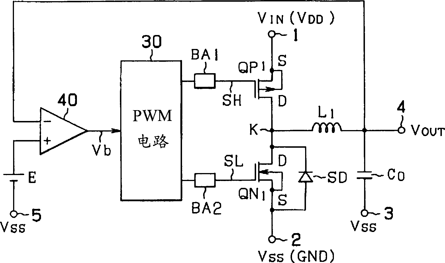
[0045] figure 1 The configuration of a power supply circuit according to one embodiment of the present invention is shown. and Figure 7 The same elements of the prior art circuits are denoted by the same reference numerals.

[0046] exist figure 1 Among them, the power supply circuit is composed of a DC-DC conversion circuit, and the DC-DC conversion circuit is composed of a synchronous rectification switching regulator circuit. The synchronous rectification switching regulator circuit has a high-frequency transistor between the input voltage VIN and the reference potential VSS ( QP1) and the low-frequency transistor (QN1), use the PWM signal to make these transistors turn on and off alternately, and output the DC voltage VOUT; the error amplifier 40 compares the output voltage of the DC-DC conversion circuit with the voltage value of the reference voltage E to obtain An error signal;...


PUM


Abstract

The invention provides a power supply circuit and a PWM circuit capable of performing PWM control within the range of 0-100% working ratio and capable of high-speed response, including: a DC-DC conversion circuit, which is connected in series to the power input terminal 1 and the reference potential input terminal The PMOS (QP1) and NMOS (QN1) between 2 are respectively turned on alternately with the PWM signal, so as to obtain the DC output voltage controlled by the PWM as the output; the error amplifier 40, which performs the DC output voltage and the reference voltage compare, and then output an error voltage; and the PWM circuit 30, which performs PWM control within the range of 0-100% duty ratio according to the error output of the error amplifier 40, wherein, the PWM circuit 30 adopts the first and the second half cycles of interleaving Divide-by-two clock pulses generate triangular wave signals with alternate half periods through the charge and discharge circuits used to generate the triangular waves, and use the triangular wave signals as the first and second PWM signals, which are converted by the first and second Schmitt trigger circuits After they are mixed, a PWM signal is generated.

Description

technical field [0001] The present invention relates to a power supply circuit and a PWM circuit, in particular to monitoring the change of the output voltage to obtain an error signal in a synchronous rectification power supply circuit. signal, and can expand the output voltage control range of the power supply circuit and PWM circuit. Background technique [0002] In recent years, mobile office equipment such as mobile phones have become popular, and the probability of using batteries to drive load circuits has increased, which inevitably requires low power consumption of power supply circuits. In addition, it is also essential that the power supply circuit responds at high speed with respect to the load circuit. [0003] In particular, with the spread of electronic equipment using integrated circuits, it is necessary to use low-voltage, low-power consumption, and stable DC power supplies. [0004] In response to changes in load and input, if the power supply is stabiliz...

Claims


Application Information

Patent Timeline
Patent Type & Authority Applications(China)
IPC IPC(8): H02M3/155H02M3/158
CPCH02M3/158H02M3/1588Y02B70/10
Inventor 西牧辰夫
Owner SEIKO EPSON CORP
Why Eureka
Try Eureka