Integrated circuit macro-module layout design based on module deformation and placement method

A technology of layout planning and integrated circuits, which is applied in the fields of circuits, electrical components, and electrical solid devices, and can solve problems such as limited scale of processing problems and poor stability of methods

Inactive Publication Date: 2003-10-15
TSINGHUA UNIV
View PDF0 Cites 7 Cited by
  • Summary
  • Abstract
  • Description
  • Claims
  • Application Information

AI Technical Summary

Problems solved by technology

These methods either deal with a very limited scale of problems, or the stability of the method is poor
Judging from the obtained results, there is still a very large gap with the actual application.

Method used


Image

  • Integrated circuit macro-module layout design based on module deformation and placement method
  • Integrated circuit macro-module layout design based on module deformation and placement method
  • Integrated circuit macro-module layout design based on module deformation and placement method

Examples


Embodiment 1

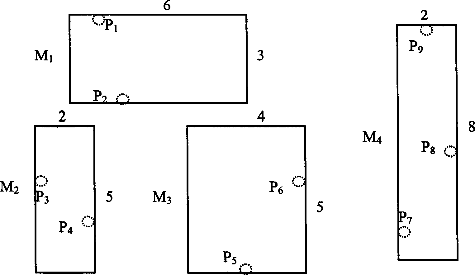
[0078] Implementation Example 1: It is used to illustrate how to construct the initial topology and corresponding layout according to the original problem, and calculate the estimated value of the line length.

[0079] Suppose the layout problem of n modules: module set M={M i (w i , h i ) / i∈[1..n]}, (w i , h i ) for module M i The width and height of ; suppose there are m lead ends (at the boundary of the module), and all lead ends PIN = { p j i ( pin _ x j i , pin _ y j i ) / j∈[1...m], i∈[1...n]}, where j is the lead end label, i is the module number to which the lead end belongs, for Relative to the coordinates of the lower left corner of the module i whe...

Embodiment 2

[0084] Embodiment 2: use the international benchmark test circuit example MCNC ami33.yal as an example combination Figure 9 The module layout is carried out with the method of the present invention. Figure 10 shows the solutions of all approximation problems during the solution process. The initial test layout is shown in Figure 10.0, and the corresponding module size and coordinates are shown in Table 1. The module coordinates in the final layout of the approximation problem with approximation factor α = 6 are shown in Table 2. See Table 3 for the original module size and final layout coordinates. See Table 4 for the lead end coordinates of some modules in the layout of α=6. When α=1, the coordinates of the lead ends of some modules are shown in Table 5. In this embodiment, the size of the module in the approximate problem of α=6 and the coordinates of the module and some lead end coordinates in the solution of the approximate problem are calculated. When the approximate...


PUM


Abstract

The present invention belongs to the computer-aided design of module level layout and features that based on the original problem, and through altering the module size and corresponding lead line position, or module deformation, one serial simple layout problems successively approximating original problem are created and solved. During the successive approximation, one approximating factor Alphais used to control the module deforming degree, and the serial problems are solved successively in the order of increasing approximating degree or decreasing Alpha from the simplest approximated problem until Alpha of 1, that is, the module size is equal to that of original module or the approximated problem is the original problem itself. Meanwhile, the solution structure of the present problemis used as the initial solution structure of the next approximated problem. The algorithm is stable, efficient and has best result obtained and industrial application value.

Description

technical field [0001] The layout planning and layout method of integrated circuit macromodule based on module deformation belongs to the field of computer aided design of integrated circuits, especially the field of BBL (Building Block Layout). Background technique [0002] In the layout of integrated circuits, hierarchical layout design, module reuse technology, a large number of applications of intellectual property modules, system-on-chip (especially digital-analog hybrid system-on-chip design), and analog circuit device-level layout issues, etc., these problems can be solved. It comes down to the layout planning and layout of integrated circuit macromodules, that is, Building Block Layout: the layout of BBL mode, which has become a current research hotspot. The above module-level layout problem can be transformed into a large-scale combinatorial optimization problem. The block-level layout (BBL) can be simply described as: [0003] There is a collection of n rectangul...

Claims


Application Information

Patent Timeline
Patent Type & Authority Applications(China)
IPC IPC(8): G06F17/50H01L21/82H01L27/00
Inventor 董社勤洪先龙陈松周硕
Owner TSINGHUA UNIV
Why Eureka
Try Eureka