Terminal box apparatus for solar energy battery module

A technology of solar cells and terminal boxes, applied in photovoltaic modules, roofs using tiles/slate tiles, roofs using flat/curved panels, etc., can solve problems such as reducing the service life of peripheral components

Inactive Publication Date: 2003-10-22
SUMITOMO WIRING SYST LTD
View PDF0 Cites 12 Cited by
  • Summary
  • Abstract
  • Description
  • Claims
  • Application Information

AI Technical Summary

Problems solved by technology

In this way, the service life of peripheral components will be reduced

Method used


Image

  • Terminal box apparatus for solar energy battery module
  • Terminal box apparatus for solar energy battery module
  • Terminal box apparatus for solar energy battery module

Examples


no. 1 example

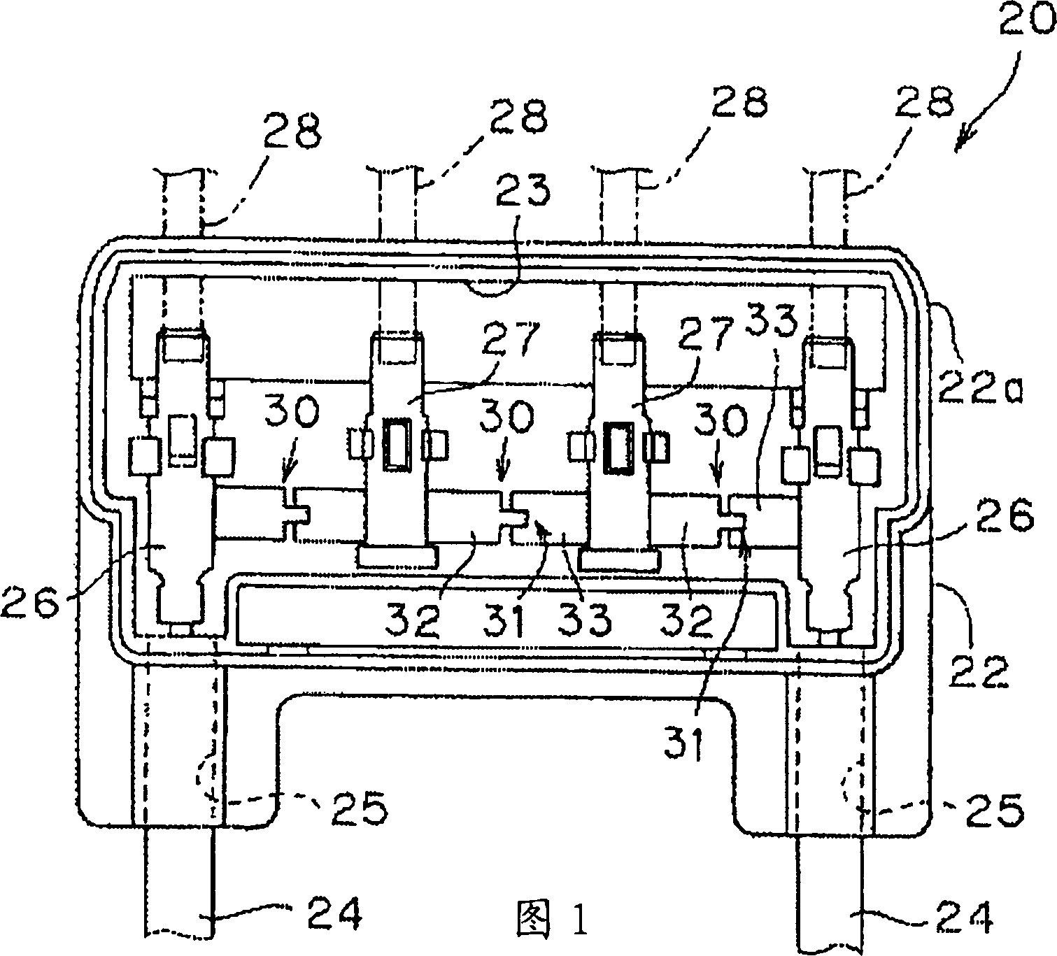
[0047] FIG. 1 shows a terminal box arrangement 20 for a solar cell module. As described above, the terminal box device 20 is located on the back of the solar cell module, and the solar cell (battery pack) is formed on the surface of the module. The solar cells function as photoelectric conversion elements connected in series.

[0048] The terminal box device 20 has a box 22 formed by molding synthetic resin. The box 22 is a roughly rectangular box body 22a, the box body has an accommodating space and an open upper surface. The case 22 also has a plate-shaped cover (not shown) mounted on the upper surface of the case body 22a so as to cover the accommodation space.

[0049] Similar to the conventional structure, the lower surface of the box body 22a of the terminal box device 20 is glued to the back of the solar cell module box body with an adhesive. In order to protect against water, moisture, heat radiation and condensation, the cover is glued to the case body 22a by silic...

no. 2 example

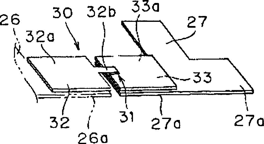
[0061] Figure 4 A bypass diode 30 of a second embodiment is shown. Components in the second embodiment that are the same as those in the first embodiment are denoted by the same symbols as in the first embodiment, and their descriptions are omitted.

[0062] In the second embodiment, in the vicinity of the protruding portion 32b of the guide plate 32 of the bypass diode 30, the guide plate 32 is cut from both sides in the direction of extension (length) of the guide plate so as to be perpendicular to the guide plate. The direction of extension (width) of 32 forms two deep slits 35, thereby forming a Z-shaped portion 32c.

[0063] A rectangular portion without the notch 35 is used as the heat radiation portion 32a. The guide plate 32 is made of metal, and its thickness is less than 0.1mm. Similar to the first embodiment, in bypass diode 30, heat radiation portions 32a and 33a are welded in layers to heat radiation portion accommodating members 26a and 27a protrudingly forme...

no. 3 example

[0067] Figure 5 A third embodiment is shown. Components of the third embodiment that are the same as those of the first embodiment are denoted by the same symbols as those of the first embodiment, and their descriptions are omitted.

[0068] In the third embodiment, the heat radiation portions 32a and 33a of the guide plates 32 and 33 of the bypass diode 30 are respectively welded on the heat radiation portion accommodating elements 26a and 27a of the connection terminals 26 and 27, placed on the heat radiation portions 32a and 27a. A rectangular heat radiating metal plate 37 between 33a has almost the same shape and size as the heat radiating portions 32a and 33a.

[0069] Thus, the third embodiment has similar effects to the first embodiment, and improves the heat radiation effect due to the provision of the heat radiation plate 37 to increase the heat capacity.

[0070] Due to the heat radiation effect exhibited by the heat radiation plate 37, it is possible to make the ...


PUM


Abstract

A terminal box apparatus includes a box; a plurality of connection terminals connected to a plurality of lead frames extending from photoelectric conversion elements of the a solar cell module; a pair of output take-out module connection cables; and a plurality of bypass diodes extending across the adjacent connection terminals respectively. Each of the bypass diodes has a bare chip diode and a pair of parallel lead plates disposed on an upper and lower surfaces of the bare chip diode and extended in opposite directions. Each of the lead plates has wide heat radiation parts respectively at an extended side thereof. Each of the heat radiation parts is soldered to heat radiation part receiving pieces projected from each of the connection terminals in a layered state.

Description

technical field [0001] The present invention relates to a terminal box arrangement for use in solar cell modules on top of a house or the like. This application claims priority from Japanese Application No. 2002-108077 filed April 10,2002. Background technique [0002] There is known a solar power generation system that generates electric power using sunlight by arranging many solar cell modules arranged in a matrix on the roof of a house. In a solar power generation system, each solar cell module has a connection terminal box device for connecting the solar cell module with other solar cell modules. [0003] FIG. 15 shows a schematic structure of a conventional solar cell module 1 . This solar cell module is provided on its surface with a plurality of solar cells 3 (battery pack 4 ), which are connected in series. [0004] The terminal box device 5 is provided on the back of the solar cell module 1 body 1a. Such as Figure 17 As shown, the terminal box device 5 contains...

Claims


Application Information

Patent Timeline
Patent Type & Authority Applications(China)
IPC IPC(8): E04D13/18H01L31/042H01L31/048H01R9/24
CPCY02B10/20H01L31/0486H01L31/0485H01R9/2425Y02E10/50Y02B10/12H02S40/34H02S40/345Y02B10/10
Inventor 东小薗城吉川裕之
Owner SUMITOMO WIRING SYST LTD
Why Eureka
Try Eureka