
Dynamic measurement time domain compensation method

A technology of dynamic measurement and time domain compensation, applied in the direction of mitigating undesired effects, etc., can solve the problems of atmospheric and environmental conditions, limited changes in the manufacturing structure of measuring elements, and unreliable inverse filtering results.

Inactive Publication Date: 2003-11-26
BEIJING JIAOTONG UNIV
View PDF0 Cites 9 Cited by
  • Summary
  • Abstract
  • Description
  • Claims
  • Application Information

AI Technical Summary

Problems solved by technology

These methods have the following problems: in actual situations, the selection of measuring elements of different materials is often restricted by atmospheric and environmental conditions, and it is difficult to choose flexibly according to the pros and cons of dynamic performance; the manufacturing structure of measuring elements is limited, and not all situations can be achieved ; Dynamic compensation is a dynamic correction method in the frequency domain, such as: "Research on Dynamic Characteristics and Dynamic Compensation of Thin Film Thermocouples" (Acta Metrology, Vol. Journal of the University of Science and Technology, Volume 24, Issue 4, August 2000), mainly using analog circuits to form analog filters or using software to form digital filters for realization. Generally, the filters designed are of higher order, and it is difficult to implement them with analog circuits , and it is difficult to adapt to real-time measurement needs due to the complexity of the algorithm; in addition, if the dynamic compensation is an inverse filter (deconvolution) operation, it is usually a high-pass system, which amplifies the noise signal in the measurement result and affects the accuracy. Even if it becomes a divergent system, the results of inverse filtering will be less credible

Method used


Image

  • Dynamic measurement time domain compensation method
  • Dynamic measurement time domain compensation method
  • Dynamic measurement time domain compensation method

Examples


Embodiment Construction

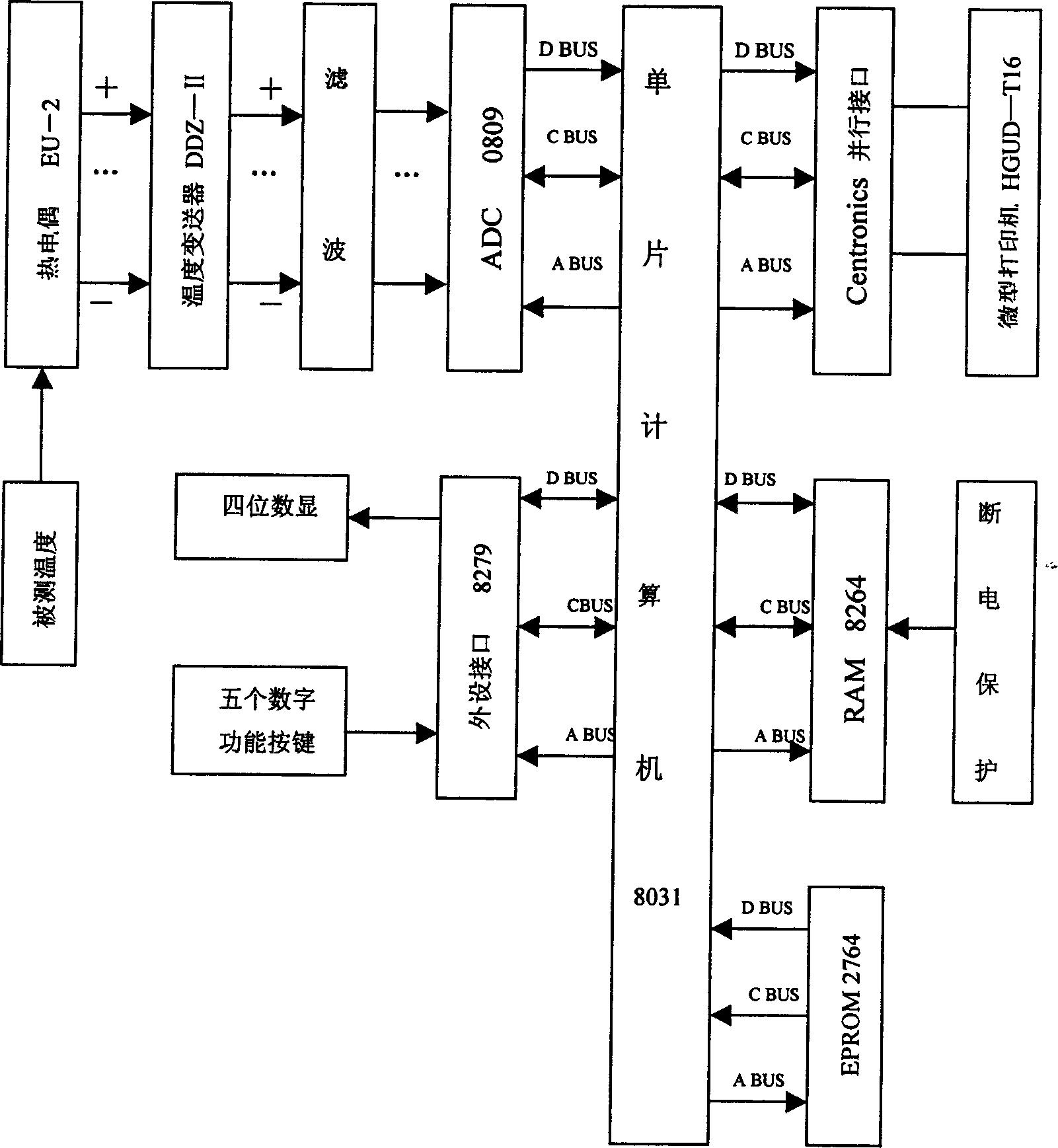
[0022] The block diagram of the hardware composition of the single-chip computer intelligent temperature measurement experimental system designed and produced according to the dynamic measurement time domain compensation algorithm is as follows: figure 1 shown. Among them, the temperature sensor adopts EU-2 type thermocouple, and connects the output terminal of the thermocouple signal with the signal input terminal of the DDZ-II temperature transmitter, so that the mA current signal output by the thermocouple during temperature measurement is converted into a standard voltage signal , in order to perform analog-to-digital conversion (ADC); connect the signal output end of the temperature transmitter to the analog signal input end of the analog-to-digital conversion integrated circuit chip ADC0809 through a low-pass filter, and the low-pass filter is composed of a resistance-capacitance circuit. For the random high-frequency interference caused by various factors in the tempera...


PUM


Abstract

The dynamic measurement time domain compensation method includes approximating the measured parameter curve into sectional broken lines and recursion calculation to obtain measured parameter based onthe kick point and slope of the broken lines. In determining the kick point and slope of a broken line, the discreet value of sensor output is calculated through analysis and recursion based on the instantaneous response of inertial link, the broken line model is then determined dynamically based the difference between the discreet value and the practical value, and the broken line signal value is finally calculated through recursion calculation based on the broken line model. The said method can raise the dynamic measurement response speed and precision, and the simple time domain recursion algorithm is simple, timely, suitable for realizing with microcomputer assemble language, low in cost, flexible and intelligent, and is suitable for measurement of various physical quantities with sensor being inertial link.

Description

1. Technical field [0001] The invention relates to a dynamic parameter measurement technology, which is especially suitable for the case where the measurement element is a first-order inertial link. 2. Background technology [0002] In general physical quantity measurement (such as temperature, humidity, atmosphere measurement, etc.), due to the inertia of the measurement element (sensor), the measurement response speed is affected, thereby affecting the dynamic measurement accuracy. This is a common and difficult problem in measurement technology. . At present, there are the following solutions: 1. Choose measuring elements made of different materials, such as the materials of commonly used humidity sensitive elements include: electrolytes, metal oxides, polymers and semiconductors, the measurement response of elements of different materials The time constants are different, distributed between the second level and the minute level. When using, try to use components with g...

Claims


Application Information

Patent Timeline
Patent Type & Authority Applications(China)
IPC IPC(8): G01D3/028
Inventor 朱刚
Owner BEIJING JIAOTONG UNIV
Learn More