New technological method-1 for detecting shear wave speed in geotechnical static and dynamic triaxial instrument

A dynamic three-axis, shear wave technology, applied in the direction of soil material testing, instruments, measuring devices, etc., can solve the problems of difficult matching, small sensor radiation energy, low electromechanical coupling coefficient, etc.

Inactive Publication Date: 2003-11-26
TIANJIN UNIV
View PDF0 Cites 9 Cited by
  • Summary
  • Abstract
  • Description
  • Claims
  • Application Information

AI Technical Summary

Problems solved by technology

This method has the following disadvantages: ①The bending unit needs to be inserted into the test piece to a certain depth (generally 3mm), which causes a certain disturbance within the range of the insertion depth, and also causes uncertainty in the propagation length of the shear wave. The error caused by the item can reach 16%; ②The near-field effect and the interference of stray waves make the first arrival of the shear wave more subjective, and the resulting measurement error can reach 30%; ③The bending unit A polarized wave is generated, and the sensitive directions of the transmitting and receiving units must be aligned in the same direction during the test to effectively receive the test signal; ④ Since the bending element needs to be inserted into the soil frequently, the insulation and waterproof problems are difficult to deal with, which also limits the service life of the device
This type of sensor has the following problems when measuring the shear wave velocity of soil samples indoors: ①Thickness shear is a high-frequency vibration mode (the vibration frequency of the chip used to make the thickness shear vibration mode of the sensor is usually greater than 400kHz), and the electromechanical The coupling coefficient is low, the radiation energy of the sensor is small, and the shear wave propagation distance is very short; ②The characteristic impedance of the PZT chip is much larger than that of the soil sample, which makes it difficult to match between the two, thereby further reducing the penetration into the soil. Shear wave energy; ③The longitudinal wave interference cannot be suppressed, especially for high-loss media such as clay and saturated loose sand, the longitudinal wave interference is very serious, which makes this method only suitable for testing the shear wave velocity of dry sand, and requires filtering Technology and certain vibration phase identification skills
Therefore, it is almost impossible to use such sensors in dynamic and static triaxial tests

Method used


Image

  • New technological method-1 for detecting shear wave speed in geotechnical static and dynamic triaxial instrument
  • New technological method-1 for detecting shear wave speed in geotechnical static and dynamic triaxial instrument
  • New technological method-1 for detecting shear wave speed in geotechnical static and dynamic triaxial instrument

Examples


Embodiment Construction

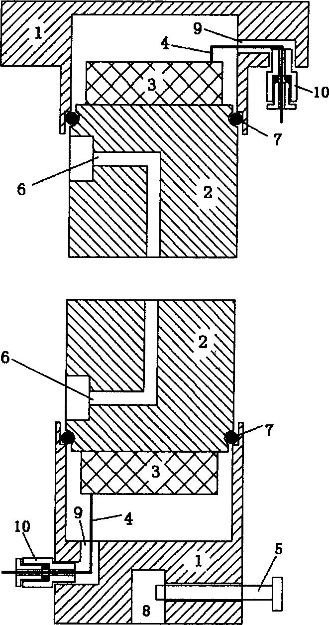
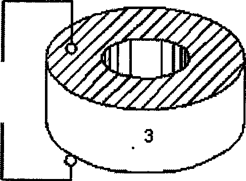
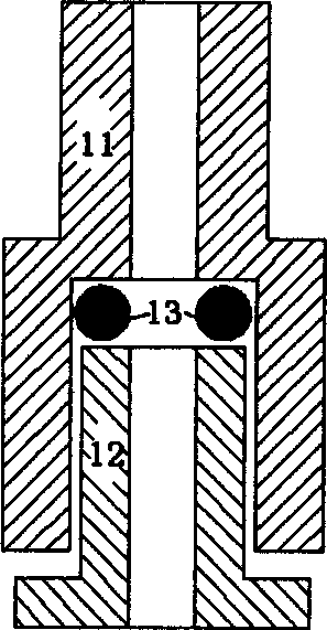
[0009] Refer to attached Figure 1~4 . The upper and lower shells are made of stainless steel or other metals, and the external dimensions are φ40mm~φ80mm×30~80mm (according to the size of the supporting triaxial instrument). Radiator is a cylinder of lightweight hard metal, the specific size matches the shell, and there is a φ3mm drainage path in the center. The vibrator is a circular ring of φ10mm~φ30mm×φ20mm~φ75mm×5mm~30mm (depending on the required vibration frequency). When assembling, first connect the upper and lower electrodes of the vibrator with the lead-out cable (4), then lead the cable out of the shell through the cable lead-out hole, and fix the cable on the shell through the cable lead-out joint. Put O-rings in the grooves of the radiator and the end of the housing. Pressurization presses the bonded radiator and vibrator into the housing.

[0010] The size of the radiator used is φ39.1mm, the height of the upper sensor (radiator and vibrator) is 50mm, the he...


PUM


Abstract

Upper and lower casings, radiator, vibrator, electric cable and other parts constitute one new kind of sensor. The radiation body is light hard metal cylinder in the height 2 cm over greater than a traditional sensor, and is used as both shearing wave radiator and the device for applying force, fixing soil sample and draining water. The vibrator is a ring made of composite PZT piezoelectrical ceramic and epoxy resin material and has upper and lower surfaces with sliver plated, upper and lower electrodes connected to cable and leading out wire junction to fix the cable to the casing. Alternately changed or pulsed voltage is applied to the vibrator to produce torsion vibration, which radiates outwards in wave form via the radiator. The present invention has the advantages of the sensor of composite piezoelectrical material and in shape suitable for measuring soil sample shearing wave speed, low vibration frequency, small volume, great radiation energy, pure shearing waveform, etc.

Description

technical field [0001] The invention relates to a geotechnical engineering testing technology. Background technique [0002] In geotechnical engineering, the shear wave velocity of the soil layer is an important soil parameter, which has been highly valued and widely used. At present, the bending element method is commonly used in geotechnical static and dynamic triaxial instruments to test the shear wave velocity. This method has the following disadvantages: ①The bending unit needs to be inserted into the test piece to a certain depth (generally 3mm), which causes a certain disturbance within the range of the insertion depth, and also causes uncertainty in the propagation length of the shear wave. The error caused by the item can reach 16%; ②The near-field effect and the interference of stray waves make the first arrival of the shear wave more subjective, and the resulting measurement error can reach 30%; ③The bending unit A polarized wave is...

Claims


Application Information

Patent Timeline
Patent Type & Authority Applications(China)
IPC IPC(8): G01N33/24
Inventor 王建华程国勇张立
Owner TIANJIN UNIV
Why Eureka
Try Eureka