Embedded capacitor structure used for logic integrated cireuit

A capacitive structure and integrated circuit technology, applied in the direction of circuits, capacitors, electrical components, etc., can solve problems such as incompatibility

Inactive Publication Date: 2003-12-03
UNITED MICROELECTRONICS CORP
View PDF0 Cites 3 Cited by
  • Summary
  • Abstract
  • Description
  • Claims
  • Application Information

AI Technical Summary

Problems solved by technology

In addition, the traditional planar capacitor structure requires three additional photomasks to respectively form the lower electrode plate 104, the d

Method used


Image

  • Embedded capacitor structure used for logic integrated cireuit
  • Embedded capacitor structure used for logic integrated cireuit
  • Embedded capacitor structure used for logic integrated cireuit

Examples


Embodiment Construction

[0019] Some embodiments of the present invention will be described in detail as follows. However, the invention may be practiced broadly in other embodiments than those described in detail, and the scope of the invention is not limited thereto but rather by the claims.

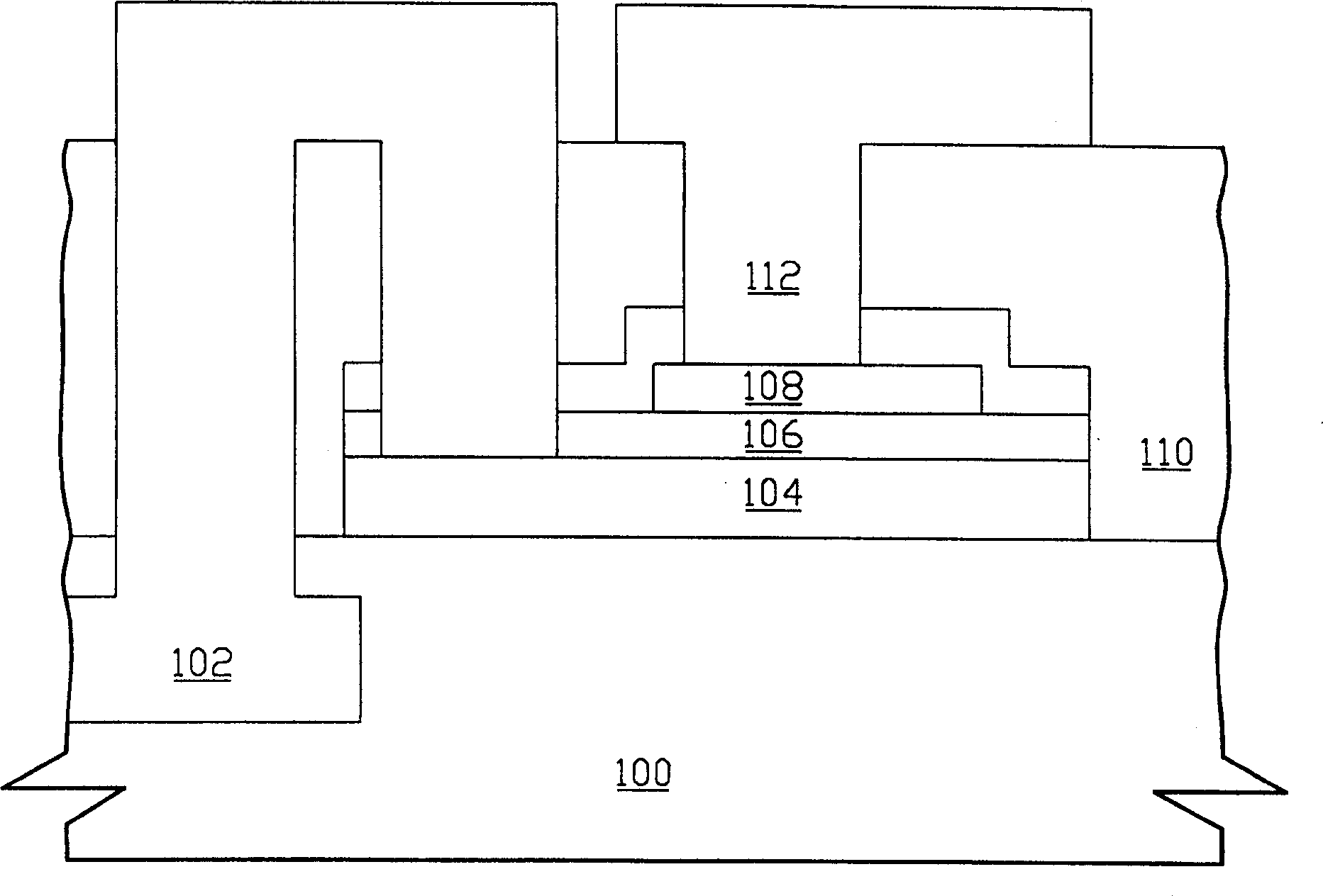
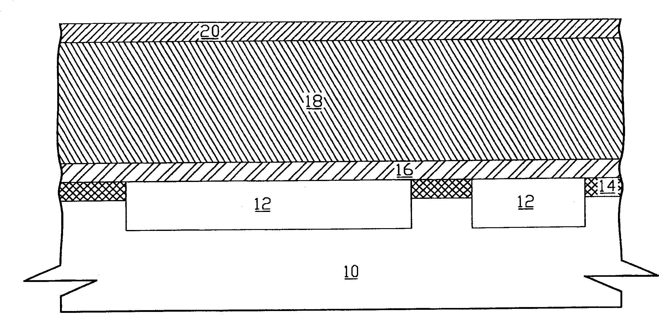
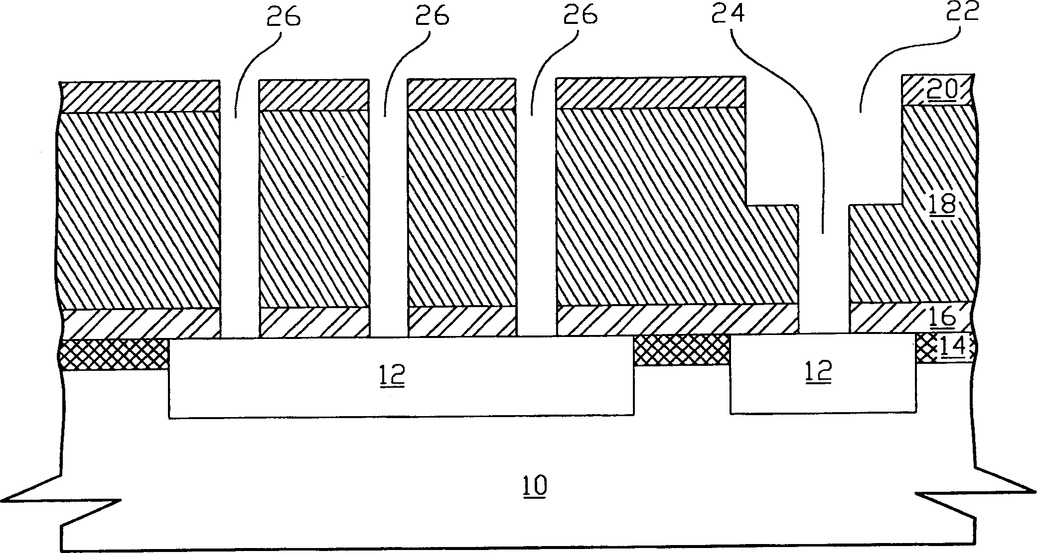
[0020] According to the present invention, a mixed-mode logic integrated circuit element is provided on a substrate, and a vertical three-dimensional metal-insulated metal capacitor structure (vertical three-dimensional MIM capacitor, vertical three-dimensional metal-insulator- metal capacitor structure) and a copper damascene structure (copper dualdamascene structure), wherein the substrate has a previous metal trace and a remaining hard mask layer. In one embodiment of the present invention, part of the previous metal wire is the first metal electrode plate (first metal electrode plate) as a vertical three-dimensional metal-insulated metal capacitor structure, and another part of the previous metal wire is ...


PUM


Abstract

A process for preparing the vertical 3D MIM capacitor structure features that a vertical 3D MIM capacitor structure compatible with the inlaid copper structure is made on base material to decrease the area of the capacitor structure in logic circuit and increase the capacitance density of the capacitors. A process for preparing an inlaid copper structure in IC in order to decrease the number of masks used in preparing said capacitor structure is also disclosed.

Description

(1) Technical field [0001] The present invention relates to a vertical three-dimensional metal-insulated metal capacitor structure, in particular to a method for manufacturing a vertical three-dimensional metal-insulated metal capacitor structure that integrates a copper inlay process and is compatible with the copper inlay process in a logic integrated circuit. (2) Background technology [0002] Precision capacitors for complementary metal oxide semiconductor (CMOS, complementary metal oxide semiconductor) analog applications are generally metal-insulated metal capacitors (MIM capacitor structure, metal-insulator-metal capacitor) or polysilicon-insulated polysilicon capacitors (PIP capacitor, polysilicon-insulator -polysilicon capacitor). [0003] However, polysilicon-insulator-polysilicon capacitors are less used due to many problems in CMOS applications. In particular, polysilicon-insulator polysilicon capacitors are generally implemented before CMOS, and heating and oxi...

Claims


Application Information

Patent Timeline
IPC IPC(8): H01L21/02
CPCH01L28/90H10B12/00
Inventor 蔡腾群许嘉麟郑懿芳林义雄
Owner UNITED MICROELECTRONICS CORP
Why Eureka
Try Eureka