Camera device and camera lens

A technology of camera lens and camera device, applied in image communication, exposure control, instruments, etc., can solve the problems of reduced peripheral opening efficiency, large back focal length, trouble, etc., and achieve the effect of miniaturization and thinning

Inactive Publication Date: 2003-12-10
CASIO COMPUTER CO LTD
View PDF0 Cites 3 Cited by
  • Summary
  • Abstract
  • Description
  • Claims
  • Application Information

AI Technical Summary

Problems solved by technology

This is because the color filter on the CCD is located a little away from the imaging surface, and when the light is incident, the actual aperture efficiency is reduced, so especially in the recent high-sensitivity CCD, most of the micro The lens array is arranged directly in front of the imaging surface, and the same is true at this time. If the exit pupil is not far enough away, the efficiency of the peripheral aperture will decrease.
[0009] 3. Requires a large back focus
[0012] However, in such an imaging device, since the shutter unit is disposed between the imaging lens and the imaging element, the shutter unit is restricted by the imaging lens and the imaging element, so the design and manufacture of the shutter unit are complicated and cumbers

Method used


Image

  • Camera device and camera lens
  • Camera device and camera lens
  • Camera device and camera lens

Examples


Embodiment 1

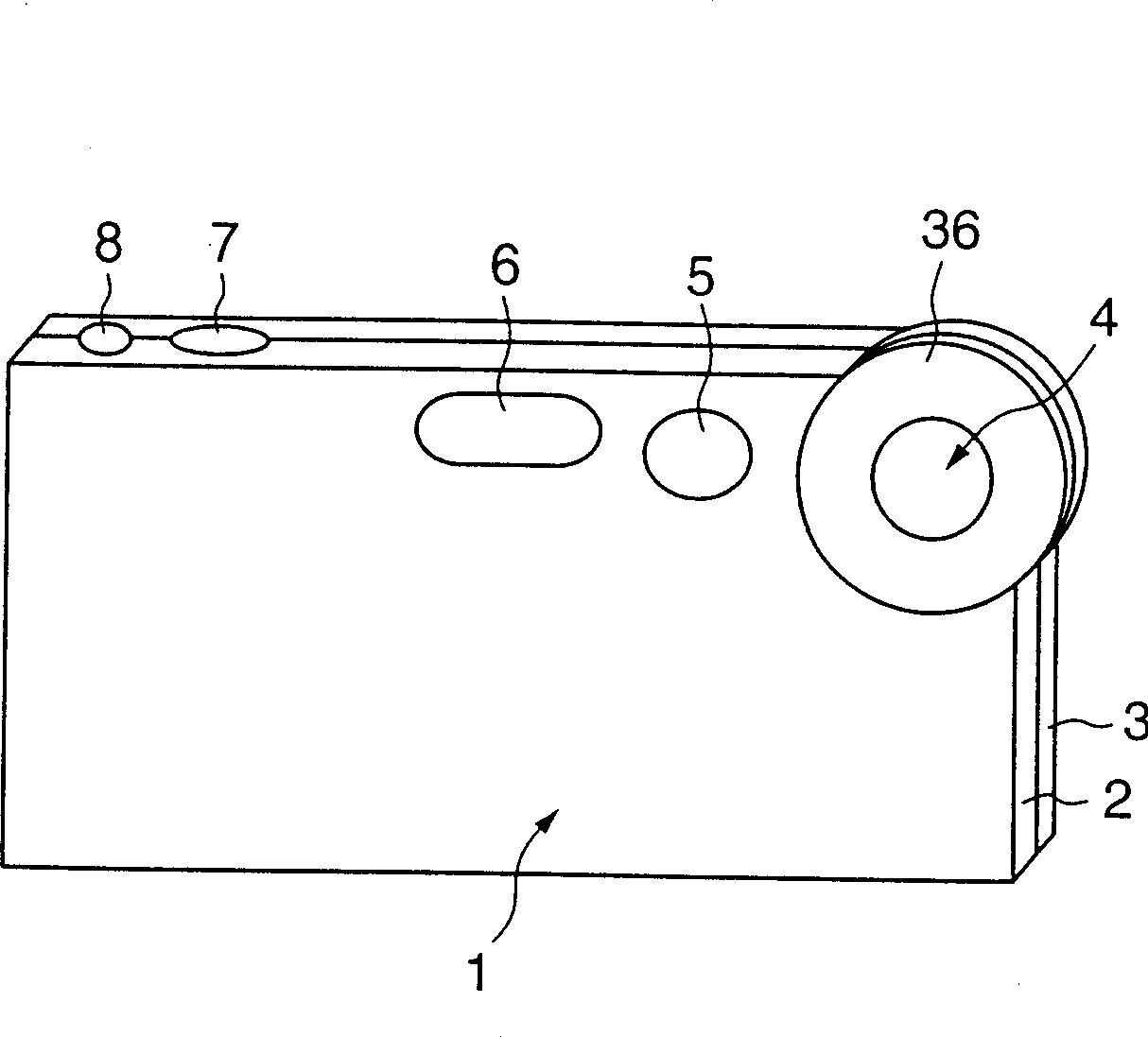
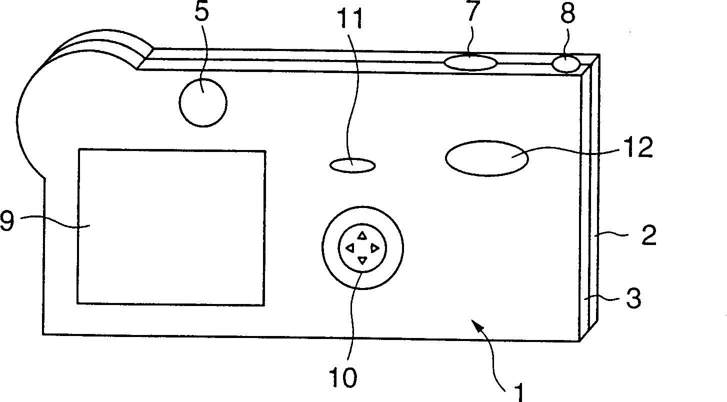
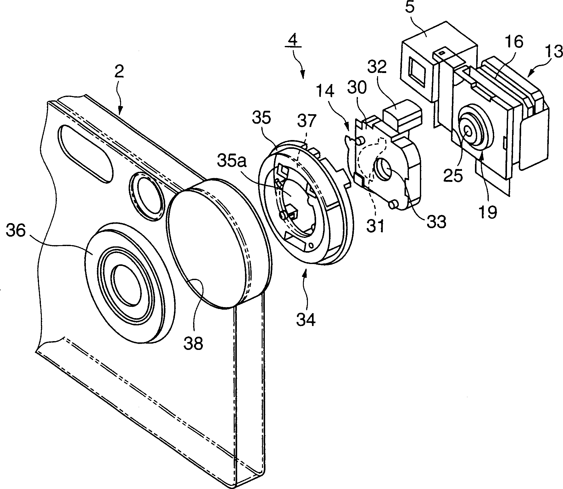
[0038] Below, refer to Figure 1 to Figure 5 One embodiment of an imaging device in which the present invention is applied to a video card will be described.

[0039] figure 1 Shown is a perspective view of the cassette camera of the present invention from the front side, figure 2 Shown is a perspective view of the cassette camera of the present invention from the rear side, image 3 Shown is figure 1 An exploded oblique view of the main parts, Figure 4 yes image 3 side view of Figure 5 Shown is image 3 An enlarged oblique view of the camera unit.

[0040] Such as figure 1 with figure 2 As shown, the card camera has a camera 1 main body 1 . The camera body 1 is composed of a front case 2 and a rear case 3, and either of the front case 2 and the rear case 3 is formed of a thin plate made of a highly rigid metal such as stainless steel.

[0041] This situation, such as figure 1 As shown, a photographing device 4 is provided at the upper right corner of the front ...

Embodiment 2

[0055] Next, refer to the following Figure 6 to Figure 9 The photographic optical system related to the present invention will be described.

[0056] The imaging lens of the present invention is characterized in that the back focus is set relatively short by arranging an infrared light absorption filter on the subject side of the imaging lens in an imaging optical system using an imaging element such as a CCD. .

[0057] Table 1 shows the existing example of disposing the infrared light absorption filter between the imaging lens and the imaging element, and the design of disposing the infrared light absorption filter of the present invention on the side closest to the subject of the imaging lens. Comparison of the full length (TL) of an example. The total length TL on the optical axis of the conventional example is -16.59 mm, and the total length TL of one embodiment is 15.76 mm. Their difference of 0.83mm is the effect of the present invention, and it can be proved that t...


PUM


Abstract

The object of the invention is to easily manufacture a shutter member without being constrained by an imaging lens and an image pickup element and to protect the imaging lens when a user does not photograph. The shutter member 14 is disposed on the side of an object of the imaging lens 25. Then, the shutter member is easily designed and manufactured, while the shutter member is not constrained by the imaging lens and the image pickup device, thereby attaining the miniaturization and thinness of the shutter member, accordingly attaining the miniaturization and thinness of the entire camera. When the camera is not used for photographing, the shutter member protects the imaging lens. In this case, arranging the shutter member as a different configuration on the side of the object of an imaging unit 13 obtained by uniting the imaging lens 25 with the image pickup device into one body makes it easy to adjust the position of the shutter member with respect to the imaging unit. This facilitates assembling work of the imaging unit and the shutter member with high accuracy, thereby improving the productivity.

Description

field of invention [0001] The present invention relates to a digital camera (DSC), a card camera (camera), a portable phone, a surveillance camera, a PC camera (camera attached to a personal computer), and also relates to a small High-performance compact camera lenses used in camera devices. Background technique [0002] For example, in an imaging device used in a cassette camera, an imaging lens, an imaging element such as a CCD, and a mechanical shutter member are provided. The image of the object to be photographed is captured by the imaging lens and projected onto the imaging element, and the projected image is converted into an electrical signal by the imaging element and taken out as image data. [0003] Here, if you pay attention to the imaging lens of the existing digital video camera (DSC), you will find that it is similar in structure to the imaging lens for VTR because it uses a CCD to capture images with high resolution. However, in terms of resolution and imag...

Claims


Application Information

Patent Timeline
IPC IPC(8): G03B9/02G03B9/08G03B17/02G03B19/02
CPCG03B9/08G03B7/093G03B30/00H04N23/50
Inventor 川上悦郎片贝智
Owner CASIO COMPUTER CO LTD
Why Eureka
Try Eureka