Device for recycling exhaust air and cooling fluid of condensator for evaporative cooling electric motor

An evaporative cooling and recovery device technology, applied in cooling/ventilation devices, electromechanical devices, electrical components, etc., can solve problems such as location restrictions, small space for evaporative cooling motors, and no condenser exhaust and coolant recovery devices. achieve the effect of avoiding leakage

Inactive Publication Date: 2003-12-24
INST OF ELECTRICAL ENG CHINESE ACAD OF SCI
View PDF2 Cites 10 Cited by
  • Summary
  • Abstract
  • Description
  • Claims
  • Application Information

AI Technical Summary

Problems solved by technology

However, at the same time as the air is discharged, part of the cooling medium steam is also discharged, which is not allowed in some applications, such as the space for installing evaporative cooling motors on ships is relatively narrow, and the location is limited
[0003] Chinese invention patent applications 01131399.4 and 01131397.8 provide two types of evaporative cooling devices for large motors. In their evaporative cooling circuits, there are no condenser exhaust and cooling liquid recovery devices

Method used


Image

  • Device for recycling exhaust air and cooling fluid of condensator for evaporative cooling electric motor
  • Device for recycling exhaust air and cooling fluid of condensator for evaporative cooling electric motor

Examples


Embodiment Construction

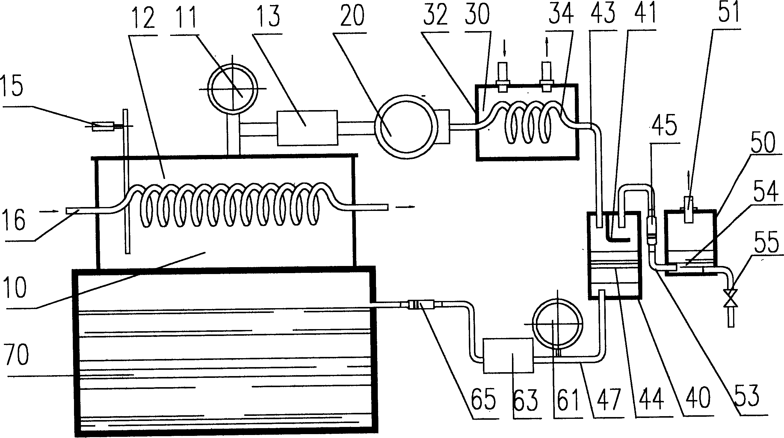
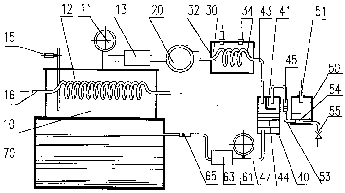
[0010] figure 1 is an embodiment of the present invention. The heat-generating parts of the stator of the evaporative cooling motor are immersed in the evaporative cooling chamber 70 , and the main condenser 10 is located above the evaporative cooling chamber 70 . The device of the present invention is installed between the main condenser 10 and the evaporative cooling chamber 70 .

[0011] The main condenser 10 is a box body, and the cooling water pipe 16 passing through the secondary cooling water runs through the box body. The upper part of the inner space of the box body is a condensation space 12, and there is a pressure controller 11 and a water leakage detector 15 above the condensation space 12 outside the box body. . In this embodiment, the pressure controller 11 selects YZX-150 electric contact pressure vacuum gauge, which has pressure display, pressure upper limit, pressure lower limit setting and corresponding electric contact. Water leakage detector 15 can be p...


PUM


Abstract

The invented device is installed between the main condenser and the evaporative cooling chamber for dipping stators. A pressure controller is installed at the top part of the main condenser and connected to its condensation space. The pressure controller is connected to the solenoid valve, the air pump, auxiliary condenser and the tank for separating air and liquid. The separated air through a one-way valve entering into the air filter is discharged after filtering. The liquid cooling medium (coolant) condensed in the said tank through the lower tube with installed another pressure controllerand solenoid valve runs back to the evaporative cooling chamber. When the pressure in the condensation space is higher than the set value, the air in the main condenser is discharged out. The invention makes the condenser operate at presetting pressure and recycles coolant so as to meet the requests of safe and economical running.

Description

technical field [0001] The invention belongs to a motor cooling device, relates to the improvement and completion of an evaporative cooling motor, and provides a condenser exhaust and cooling liquid recovery device. Background technique [0002] Large-scale generators, including turbo generators and hydro generators, adopt evaporative cooling technology, which has the advantages of better cooling effect, safe and reliable operation, etc. than commonly used air-cooled, water-cooled, and hydrogen-cooled units. Here, the generator whose stator heating element adopts evaporative cooling is called an evaporative cooling motor. Its evaporative cooling device is a closed cooling medium circulation system. In the stator evaporative cooling chamber of the motor, the liquid cooling medium (also called cooling liquid) After the stator of the motor heats up, the boiling evaporation phase turns into a vapor, enters the condenser to exchange heat with the secondary cooling water, condense...

Claims


Application Information

Patent Timeline
Patent Type & Authority Applications(China)
IPC IPC(8): H02K9/20
Inventor 钱光岳顾玉兰顾国彪国建鸿田新东熊楠
Owner INST OF ELECTRICAL ENG CHINESE ACAD OF SCI
Why Eureka
Try Eureka