Eureka AIR delivers breakthrough ideas for toughest innovation challenges, trusted by R&D personnel around the world.

High-efficiency dc motor improved structure

A DC motor, improved structure technology, applied in the direction of DC commutator, collector, electrical components, etc., can solve the problems affecting the range of DC motor use, commutator and brush wear, limited winding range, etc., to achieve Good heat dissipation, low starting current and long service life

Inactive Publication Date: 2004-01-07
郭一羽
View PDF0 Cites 0 Cited by
  • Summary
  • Abstract
  • Description
  • Claims
  • Application Information

AI Technical Summary

Problems solved by technology

[0002] The structure of commonly used motors can usually be divided into two parts: the rotor and the stator. The rotor is mainly a rotating part composed of a rotatable armature, brushes, and a commutator, and a coil is wound on the armature; and the stator It is composed of magnetic poles, intermediate poles, casings, end frames and brackets; when the stator and rotor are combined, the coils wound around the armature can generate a force to drive the rotor of the motor to engage in positive and negative rotation Rotation, however, such an arrangement will cause the wear and tear of the commutator and brushes during the rotation of the rotor and the generation of spark noise when driven by a large current, and the coils wound on the armature are enclosed in the stator , This will also cause disadvantages such as difficult heat dissipation of the coil and limited winding range. Therefore, the motor is hindered by the above restrictions, and it is inconvenient whether it is manufactured by the industry or used by the user, so it also indirectly affects DC. Therefore, how to make a motor that can improve the above shortcomings is a top priority
[0003] It can be seen that the above-mentioned commonly used articles still have many shortcomings, which are really not a good design, and need to be improved urgently.

Method used


Image

  • High-efficiency dc motor improved structure
  • High-efficiency dc motor improved structure
  • High-efficiency dc motor improved structure

Examples


Embodiment Construction

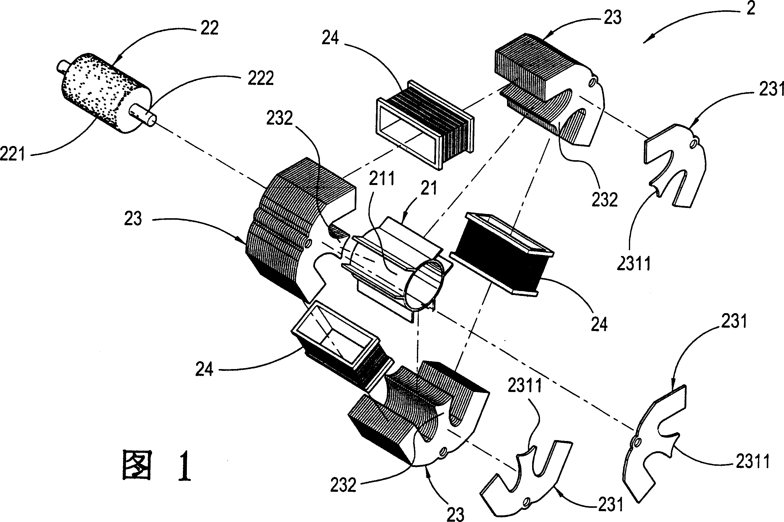
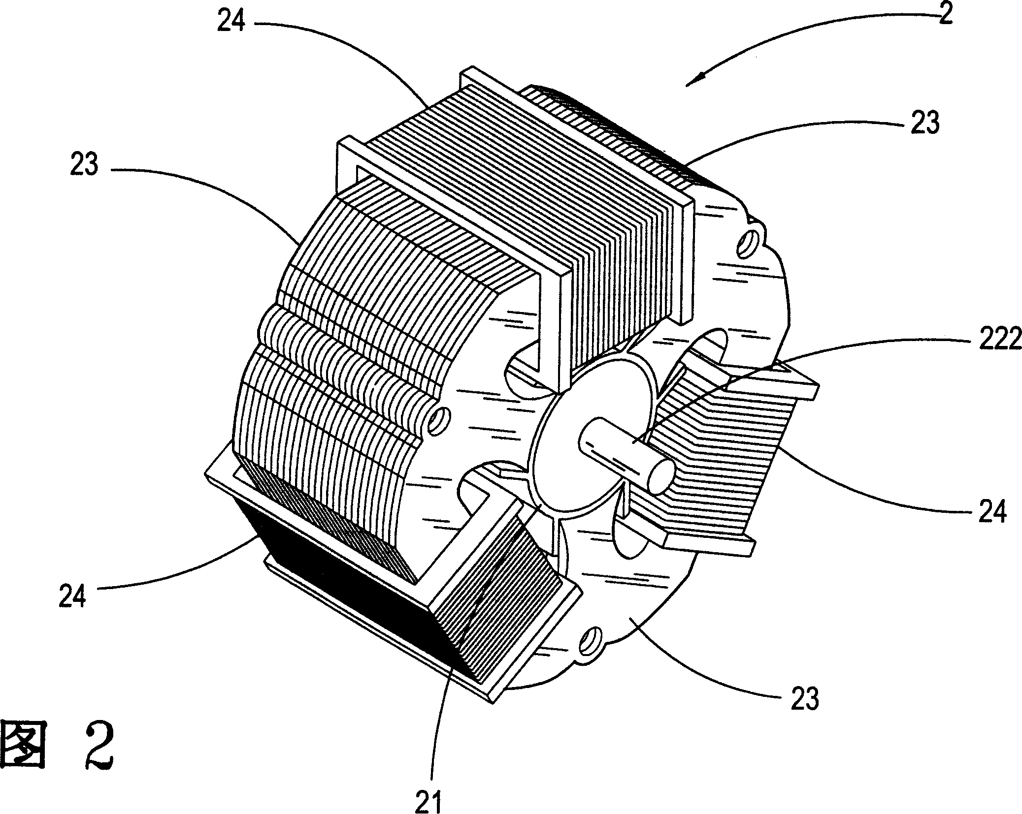
[0028] The invention is an improved structure of a high-efficiency DC motor, which is composed of an inner magnetic motor and a control module.

[0029] Please refer to Fig. 1 and Fig. 2, which are exploded schematic diagrams and physical schematic diagrams of the internal magnetic motor. It can be seen from the figures that the internal magnetic motor 2 mainly includes:

[0030] A non-metallic magnet seat 21, which is provided with three standard grooves 211 in equal parts outside the non-metallic magnet seat 21;

[0031] An axis 22, the axis 22 is composed of a magnet 221 and a power center shaft 222, the power center shaft 222 runs through the central part of the magnet 221, so that the center shaft 222 protrudes from the two ends of the magnet 221, and The central axis 222 will extend to the control module;

[0032] Three silicon steel sheet groups 23 are formed by stacking several silicon steel sheets 231. The central part of the silicon steel sheet 231 has a protruding ...


PUM


Abstract

A high efficient DC motor reformed structure is composed of an intrinsic motor and a control module in which, the intrinsic motor is to put the shaft core through a heteroscedasticity magnet then to be put in a nonmetal magnet seat and design three normal grooves evenly outside the seat for plugging and connecting stacked silicon steel sheet set wound by magnetic field coils to become a three-phase DC motor influenced by the action force generated by magnetic field coils and the control module set links with the motor in series to drive and control action and direction of the motor.

Description

technical field [0001] The invention relates to an improved structure of a high-efficiency direct-current motor, in particular to an improved structure of a direct-current motor with a control module so that the internal magnetic motor has high power output characteristics. Background technique [0002] The structure of commonly used motors can usually be divided into two parts: the rotor and the stator. The rotor is mainly a rotating part composed of a rotatable armature, brushes, and a commutator, and a coil is wound on the armature; and the stator It is composed of magnetic poles, intermediate poles, casings, end frames and brackets; when the stator and rotor are combined, the coils wound around the armature can generate a force to drive the rotor of the motor to engage in positive and negative rotation Rotation, however, such an arrangement will cause the wear and tear of the commutator and brushes during the rotation of the rotor and the generation of spark noise when d...

Claims


Application Information

Patent Timeline
Patent Type & Authority Applications(China)
IPC IPC(8): H01R39/04H02K23/00H02K23/04
Inventor 郭一羽
Owner 郭一羽
Why Eureka
Eureka Blog
Learn More