Fully automatic supersonic cleaner withs several functional sites

An ultrasonic cleaning, fully automatic technology, applied in cleaning methods and utensils, cleaning methods using liquids, chemical instruments and methods, etc., can solve the problems of low cavitation strength, corrosion, inconsistent cleaning effect, etc., to reduce pollution and improve. The effect of ultrasonic cleaning quality

Inactive Publication Date: 2004-01-21
SHAANXI NORMAL UNIV
View PDF0 Cites 23 Cited by
  • Summary
  • Abstract
  • Description
  • Claims
  • Application Information

AI Technical Summary

Problems solved by technology

[0002] The existing ultrasonic cleaning device has a single frequency, and the sound field distribution in the cleaning tank is uneven, and the cavitation intensity in some places is small. As a result, the cleaning effect of the workpiece to be cleaned is inconsistent. Even if it is cleaned by three tanks, the effect is still unsatisfactory. If the cleaning time is too long, it will also cause localized corrosion
There is no reasonable setting basis for the layout of the ultrasonic transducers of t

Method used


Image

  • Fully automatic supersonic cleaner withs several functional sites
  • Fully automatic supersonic cleaner withs several functional sites
  • Fully automatic supersonic cleaner withs several functional sites

Examples


Embodiment 1

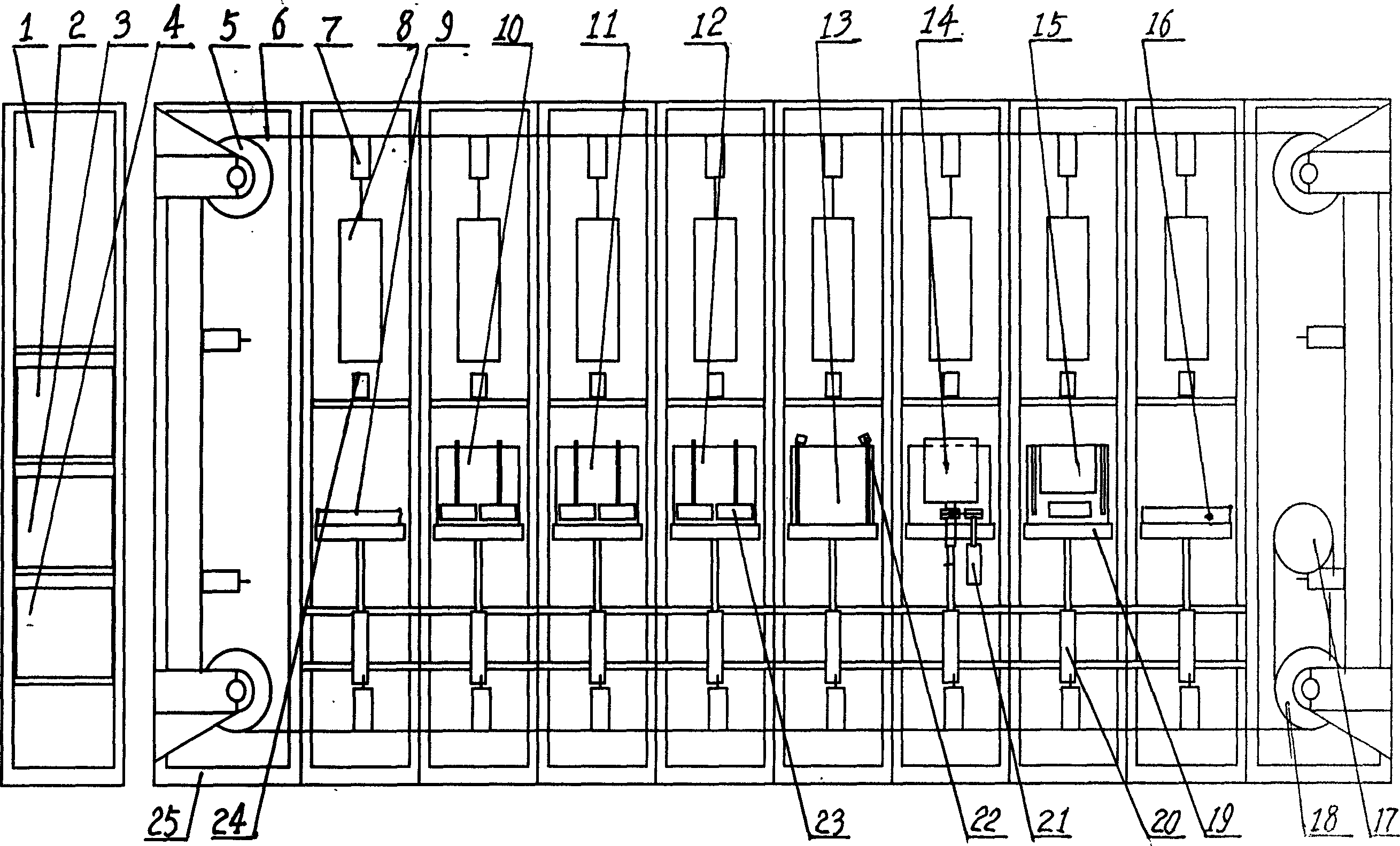
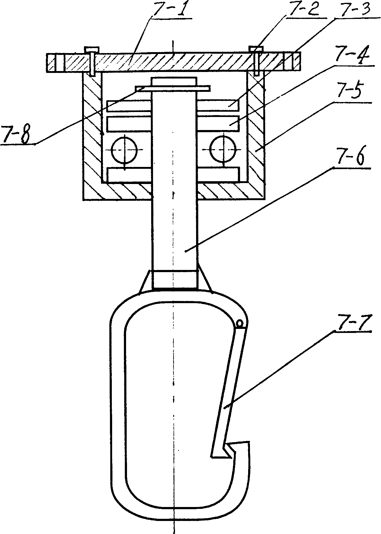
[0025] exist figure 1 Among them, the multi-station automatic ultrasonic cleaning device implemented in this implementation consists of a control cabinet 1, a high-frequency ultrasonic generator 2, an intermediate-frequency ultrasonic generator 3, a low-frequency ultrasonic generator 4, a reversing sprocket 5, a chain 6, and a rotating hanger 7 , Cleaning workpiece loading column 8, workpiece loading table 9, low-frequency ultrasonic cleaning tank 10, medium-frequency ultrasonic cleaning tank 11, high-frequency ultrasonic cleaning tank 12, shower cleaning tank 13, frequency conversion dehydrator 14, hot air generator 15, workpiece unloading table 16. Electric motor 17, driving sprocket 18, bracket 19, lifting cylinder 20, frequency conversion motor 21, shower nozzle 22, ultrasonic vibrating body 23, photoelectric sensor 24, and bracket 25 are connected to form, wherein lifting cylinder 20 is connected to bracket 19 As a lifting mechanism, the motor 17 is an embodiment of the p...

Embodiment 2

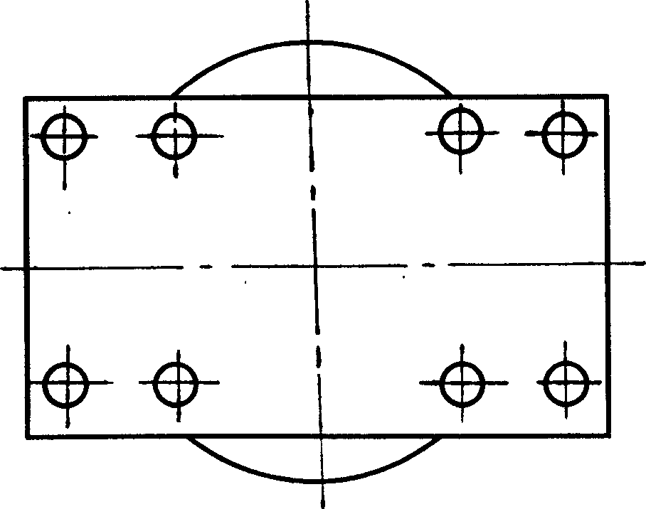
[0034] In this embodiment, the ultrasonic transducer array of the ultrasonic vibrating body 23 installed in the low-frequency ultrasonic cleaning tank 10, the intermediate-frequency ultrasonic cleaning tank 11, and the high-frequency ultrasonic cleaning tank 12 is composed of six ultrasonic transducers 23-3. . Other components and the coupling relationship of the components are the same as in Embodiment 1.

Embodiment 3

[0036] In this embodiment, the ultrasonic transducer array of the ultrasonic vibrating body 23 installed in the low-frequency ultrasonic cleaning tank 10, the intermediate-frequency ultrasonic cleaning tank 11, and the high-frequency ultrasonic cleaning tank 12 is composed of 40 ultrasonic transducers 23-3. . Other components and the coupling relationship of the components are the same as in Embodiment 1.

[0037] Working process of the present invention is as follows:

[0038] The motor 17 drives the chain 6 to rotate, the control cabinet 1 controls the lifting cylinder 20 to work, so that the loading table 9 rises, and the operator can put the workpiece into the cleaning workpiece loading column 8, the low-frequency ultrasonic cleaning tank 10, the medium-frequency ultrasonic cleaning tank 11, and the high-frequency ultrasonic cleaning tank 11. The high-frequency ultrasonic cleaning tank 12 is respectively controlled by the control cabinet 1 to work with the lift cylinders ...


PUM


Abstract

The multi-station fully automatic supersonic cleaner includes control cabinet, HF supersonic wave generator, MF supersonic wave generator and LF supersonic wave generator, as well as support, driver unit, hanging unit, workpiece basket, workpiece table on an elevating mechanism, HF supersonic wave cleaning tank, MF supersonic wave cleaning tank and LF supersonic wave cleaning tank with supersonic vibrator, rinsing tank with showering nozzle, frequency-variable dewatering device connected to a frequency-variable motor, hot blast generator and workpiece unloading table. It also includes photoelectronic sensor set on the support. It has the advantages of continuous cleaning steps, thorough cleaning, no environmental pollution, etc.

Description

technical field [0001] The invention belongs to the technical field of methods or equipment for generating or transmitting subsonic, audible or ultrasonic mechanical vibrations used in general mechanical operations, and specifically relates to the generation or transmission of subsonic, audible or supersonic vibrations by piezoelectric effect or electrostriction. methods or apparatus for mechanical vibration. Background technique [0002] The existing ultrasonic cleaning device has a single frequency, and the sound field distribution in the cleaning tank is uneven, and the cavitation intensity in some places is small. As a result, the cleaning effect of the workpiece to be cleaned is inconsistent. Even if it is cleaned by three tanks, the effect is still unsatisfactory. If the cleaning time is too long, it will also cause local corrosion. There is no reasonable setting basis for the layout of the ultrasonic transducers of the ultrasonic cleaning device, resulting in the lay...

Claims


Application Information

Patent Timeline
IPC IPC(8): B08B3/12
Inventor 牛勇张明铎任金莲
Owner SHAANXI NORMAL UNIV
Why Eureka
Try Eureka