Adjustable digital electromagnetic driven light-barrier attenuator

A technology of dimming attenuation and electromagnetic drive, applied in electromagnetic wave transmission systems, optics, instruments, etc., can solve the problems of narrow working band of attenuators, large return loss of optical filters, large polarization mode dispersion, etc., to improve working stability stability, low driving voltage, and fast stepping speed

Inactive Publication Date: 2004-02-04
ZHEJIANG UNIV
View PDF0 Cites 5 Cited by
  • Summary
  • Abstract
  • Description
  • Claims
  • Application Information

AI Technical Summary

Problems solved by technology

However, most of the general gradient optical absorption density filters are coated, and their good performance requires high coating technology, which is currently not available in China.
Due to the dependence of the gradient optical absorption density filter on the optical signal, the working band of the attenuator is narrow and the polarization mode dispersion is large, and the filter with this structure may cause a large return loss
The driving structure of this design uses a stepping motor, which not only makes the whole device structure huge, but also has a high cost.

Method used


Image

  • Adjustable digital electromagnetic driven light-barrier attenuator
  • Adjustable digital electromagnetic driven light-barrier attenuator
  • Adjustable digital electromagnetic driven light-barrier attenuator

Examples


Embodiment Construction

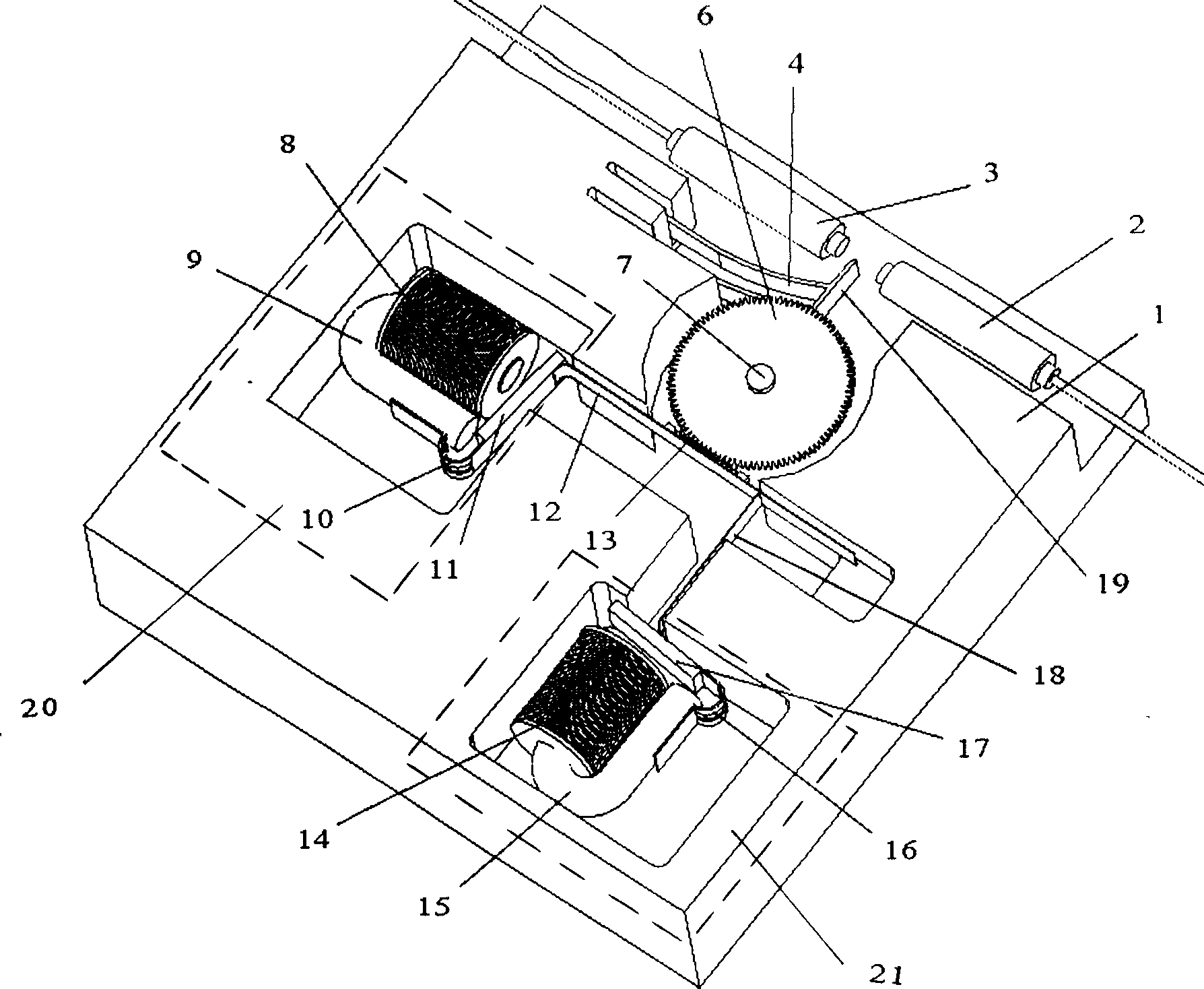
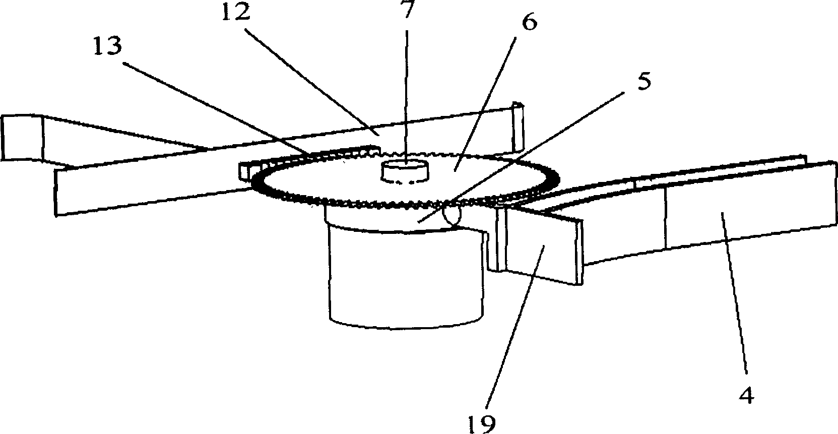
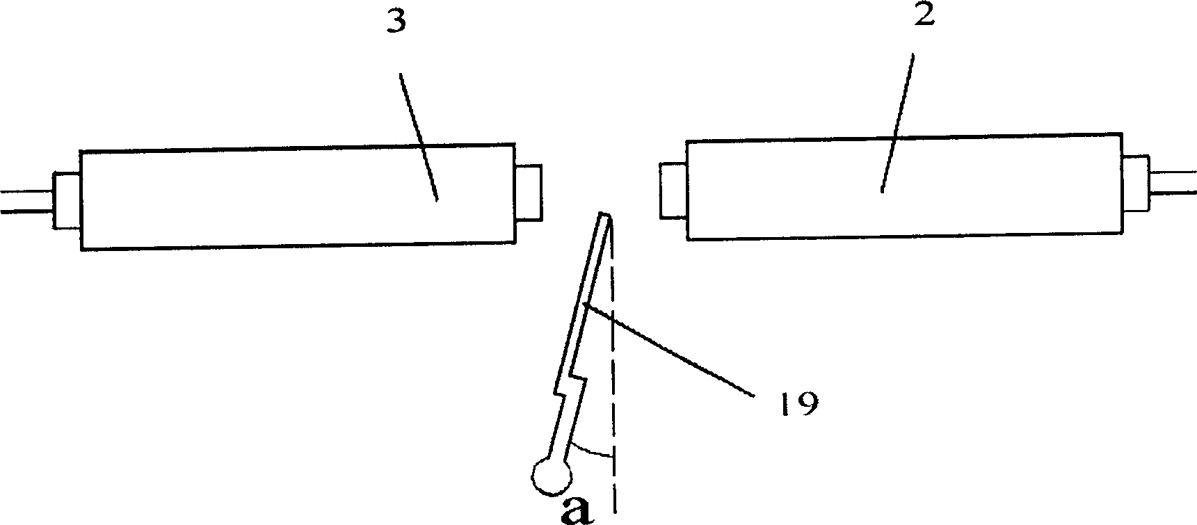
[0034] Such as figure 1 As shown, the two input and output fiber collimators 2 and 3 aligned by the coupling optical path are fixed on the substrate 1, and a light blocking sheet 19 connected to the elastic sheet 4 is arranged between the two input and output fiber collimators 2 and 3, The tail end of the light blocking sheet 19 is in point contact with the eccentric wheel 5 mounted on the rotating shaft 7 under the action of the elastic sheet 4, and the plane where the light blocking sheet 19 is located passes through the axis of the rotating shaft 7 of the eccentric wheel 5, the gear 6 and the eccentric wheel 5 are coaxially installed and fixed together, and rotate around the rotating shaft 7 vertically fixed on the base plate, and the rack 13 meshed with the gear 6 is connected to the first and second iron-nickel sheets 11 through the transverse and longitudinal elastic plates 12 and 18 respectively. , 17 connections, first and second iron-nickel sheets 11 and 17 are conne...


PUM

PropertyMeasurementUnit
diameteraaaaaaaaaa

Abstract

A attenuator comprises two input/output optical fibre collimators aligned through couple light path to be set on base with light blocking sheet between as its tail end contacted with ecentric in point-contact, light blocking sheet rotated at its level in coaxial with rotary shaft, rack bar engaged with gear to be set on leteral elastic sheet which is connected with longitudinal elastic sheet, the two connected to displacement driver separately. In the present invention, the gear and rack bar engaging mechanism is driven by the displacement driver to bring the ecentric so the light attenuation volume can be adjusted by moving the light blocking sheet.

Description

technical field [0001] The invention relates to an adjustable optical attenuator, in particular to a digital electromagnetic-driven light-shielding adjustable optical attenuator. Background technique [0002] Optical attenuator (Optical Attenuator) is one of the important optical passive devices in modern optical transmission network. Its main function is to attenuate the optical signal power passing through the device and obtain the optical power output specified by the user. In the optical transmission process, the transmitted optical power varies due to the transmission distance of the optical fiber, the number of optical fiber connections, the number of optical components used, and the performance. For various optical transmission systems, when optical switching occurs between them, the input and output optical power requirements are also different because of their different characteristics. Therefore, when the optical power received / output by ...

Claims


Application Information

Patent Timeline
Patent Type & Authority Applications(China)
IPC IPC(8): G02F1/19H04J14/02
Inventor 吴兴坤曹钟慧邹勇卓鲍俊峰
Owner ZHEJIANG UNIV
Why Eureka
Try Eureka