Drawing frame and sliver blocking sensor

A sensor, draw frame technology, used in spinning machines, textiles and paper, drafting equipment, etc.

Inactive Publication Date: 2004-02-11
RIETER INGOLSTADT SPINNEREIMASCHENBAU AG
View PDF0 Cites 0 Cited by
  • Summary
  • Abstract
  • Description
  • Claims
  • Application Information

AI Technical Summary

Problems solved by technology

[0005] The technical problem to be solved by the present invention is an improvement of the above-mentioned ty...

Method used


Image

  • Drawing frame and sliver blocking sensor
  • Drawing frame and sliver blocking sensor
  • Drawing frame and sliver blocking sensor

Examples


Embodiment Construction

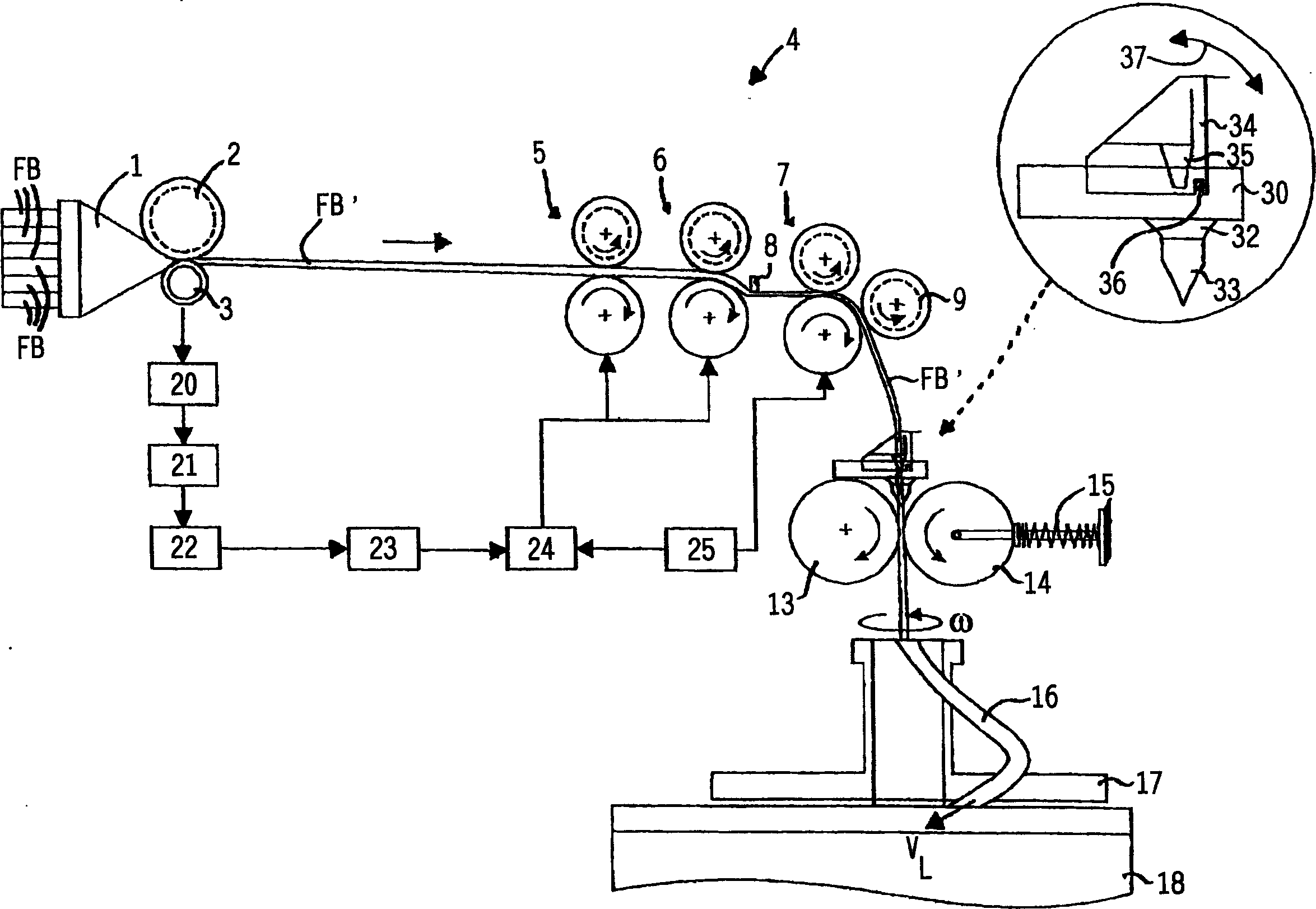
[0035] The following is based on figure 1Describe the basic operating principle of the draw frame. According to an example of the prior art, a plurality of untwisted draw frame slivers FB are fed side by side. It is also possible to feed only one fiber sliver FB to the draw frame. A trumpet head 1 of compacted fiber sliver FB is arranged at the input end of the draw frame. Other compaction devices may also be used. A compacted fiber strip FB' consisting of a plurality of individual fiber strips FB is fed into a drafting device 4 by means of a detection device 2, 3 consisting of a pair of rollers. Its drafting unit 4 generally comprises three drafting elements or roller pairs, between which the actual drafting takes place. The pairs of rollers are input roller pairs 5, intermediate roller pairs 6 and output or supply roller pairs 7, which rotate at successively increasing peripheral speeds. With such a configuration, the fiber strand FB' is drawn according to the periphera...


PUM


Abstract

Sliver emerging from the drafting system on a drawframe is fed through an inlet guide (33) to a pair of calender rollers (14) and then to a coiler head. A sensor to detect any sliver build-up, e.g. due to an obstruction in the coiler head, is situated at the exit of the guide (33), preferably mounted on the underside of guide support plate (30). An alarm signal can be produced by an optical sensor (40) that detects a reflected light beam. An Independent claim is also included for a sensor that produces an electrical alarm signal when a flexible feeler, e.g. made out of a spring or rubber, is deflected by the sliver. The sensor includes a deflecting element that diverts the fiber flow.

Description

technical field [0001] The invention relates to a drawing frame for drawing at least one fiber sliver, which has a drafting device, a sliver horn arranged after the drafting device and a pair of downstream calendering rollers, which will be drawn together in the drafting device The fiber sliver (FB) of the sliver is extracted through the sliver horn and fed into the sliver tube arranged downstream of the calender roller pair and finally falls into the can , generating a signal to stop the sliver transport. The invention also relates to a sliver jam sensor for a weaving machine, which has a deflection element which in the event of a jam deviates from a rest position into an alarm position, wherein an electrical signal for stopping the draw frame is generated in the alarm position. Background technique [0002] Draw frames with a sliver jam sensor at the output of the drafting device are known. The fiber sliver leaving the drafting unit at a speed of up to 1000 m / min must be...

Claims


Application Information

Patent Timeline
IPC IPC(8): D01H5/38D01H13/22
CPCD01H13/22D01H5/38
Inventor W·格勒
Owner RIETER INGOLSTADT SPINNEREIMASCHENBAU AG
Why Eureka
Try Eureka