Heat exchanger

A heat exchanger and condensate technology, which is applied in heat exchange equipment, indirect heat exchangers, heat exchanger types, etc., can solve the problems of reduced heat exchanger performance, reduced heat exchange performance, and prolonged condensate discharge time.

Inactive Publication Date: 2004-02-25
LG ELECTRONICS INC
View PDF0 Cites 17 Cited by
  • Summary
  • Abstract
  • Description
  • Claims
  • Application Information

AI Technical Summary

Problems solved by technology

At this time, the condensed water formed on the surfaces of the tubes 102 and the fins 110 creates air flow resistance during the heat exchange and reduces the heat exchange performance.
[0014] In addition, since the condensed water condensed on the fins 110 and the tubes 102 is discharged downward through the louvers 113 formed on the planar portion 112 of the fin 110, the condensed water discharge time is prolonged, resulting in a decrease in performance of the heat exchanger.

Method used


Image

  • Heat exchanger
  • Heat exchanger
  • Heat exchanger

Examples


Embodiment Construction

[0026] Reference will now be made in detail to the preferred embodiments of the invention, examples of which are illustrated in the accompanying drawings.

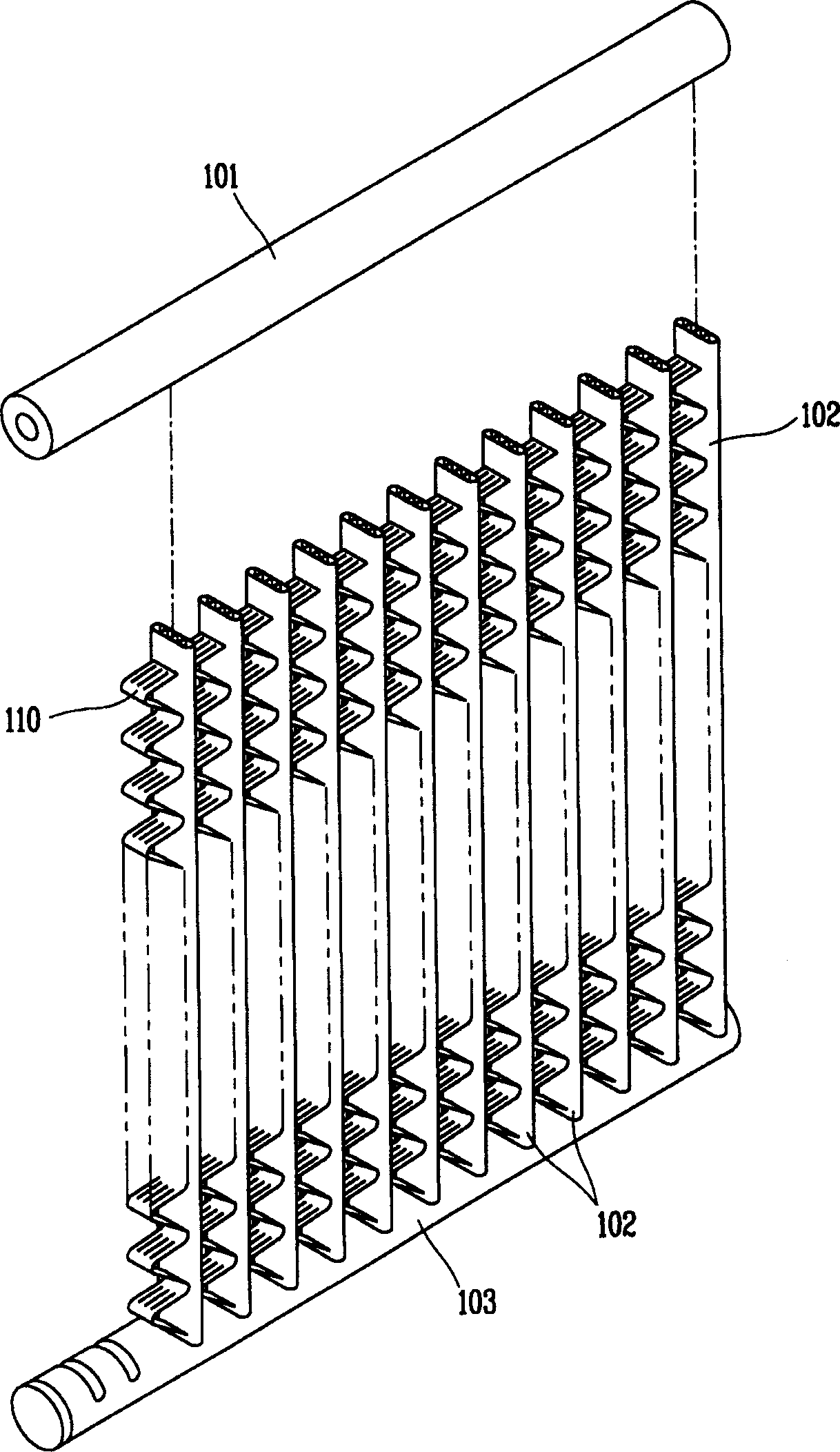
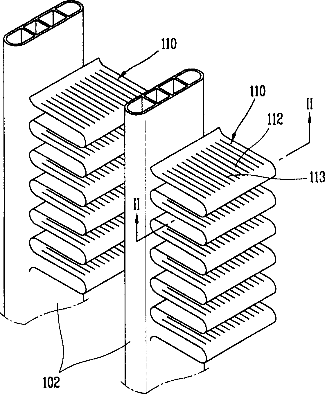
[0027] Figure 4 is a perspective view of a heat exchanger according to the present invention; Figure 5 yes Figure 4 Partial perspective view of an enlarged portion of a heat exchanger.

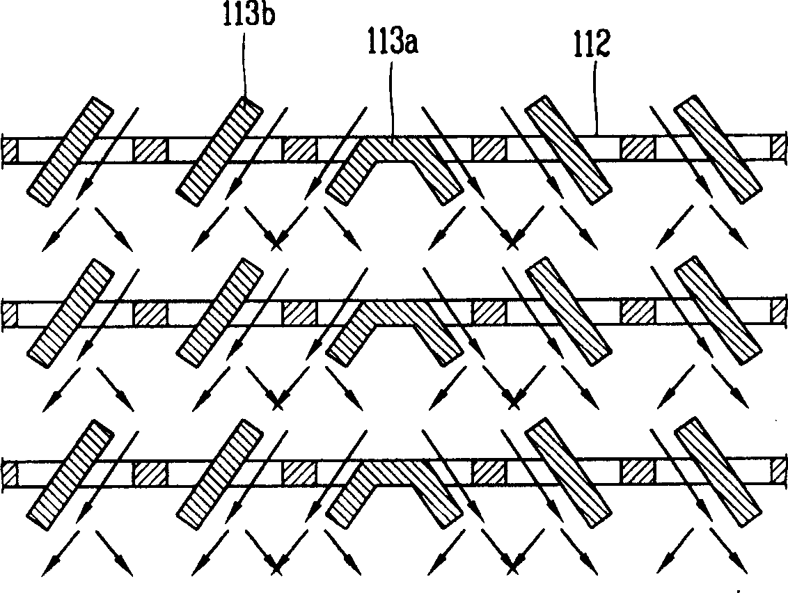
[0028] As shown in the figure, the heat exchanger of the present invention includes: a receiving pipe 1 into which fluid is introduced; a discharge pipe 3 for discharging the heat-exchanged fluid to the outside; fins 10, which are bent at regular intervals so that air can pass on their outer peripheral surfaces, and have a guide unit to guide condensed water condensed on their surfaces in one direction; and disposed between the fins 10 A tube for heat exchange between the fluid flowing through the tube and the air passing through the outer peripheral surface of the fin 10, and the tube has a condensed water discharge passage 5 to dis...


PUM


Abstract

A heat exchanger includes: a receiving tube into which a fluid is introduced; a discharge tube for discharging a heat-exchanged fluid outwardly; a plurality of pins disposed between the receiving tube and the discharge tube, being bent at regular intervals so that air can pass at an outer circumferential surface thereof, and having a guide unit for guiding condensate water condensed at the surface thereof in one direction; and a tube disposed between the pins for heat-exchanging between a fluid passing therethrough and air passing the outer circumferential surface of the pin, and having a condensate water discharge path for discharging downwardly the condensate water guided by the guide unit. A condensate water remaining phenomenon between the pins can be reduced, and thus, the heat exchanging performance is improved.

Description

technical field [0001] The present invention relates to a heat exchanger, and more particularly, to a heat exchanger capable of smoothly discharging condensed water condensed at tubes and pins of the heat exchanger. Background technique [0002] Generally, heat exchangers, that is, devices that utilize direct or indirect contact of two different fluids to exchange heat, are used as heaters, cooling, etc. in industrial fields such as heating, air conditioning, driving force generation, waste heat recovery, and chemical processing. evaporator, evaporator and condenser. [0003] Especially in a heat exchanger for an air conditioner, when air containing moisture flows through the fins of the heat exchanger, it exchanges heat with the refrigerant supplied to the tubes. [0004] That is, in the heat exchanger, when air containing moisture flows through fins having enlarged surfaces to increase their contact surface with air to enhance heat transfer, heat exchange occurs due to su...

Claims


Application Information

Patent Timeline
Patent Type & Authority Applications(China)
IPC IPC(8): F28F1/02F24F13/22F25B39/02F28D1/053F28F1/12F28F1/32F28F17/00
CPCF28F17/005F28F1/128F28D1/0535Y02P80/15F24F13/22
Inventor 高喆洙吴世允吴世基史容澈张东延
Owner LG ELECTRONICS INC
Why Eureka
Try Eureka