Paper feeding device

A paper feeding device and paper feeding technology, applied in printing devices, transportation and packaging, position/direction control, etc., can solve problems such as excessive noise, inability to control rotation and acceleration by itself

Inactive Publication Date: 2004-02-25
BROTHER KOGYO KK
View PDF0 Cites 9 Cited by
  • Summary
  • Abstract
  • Description
  • Claims
  • Application Information

AI Technical Summary

Problems solved by technology

There is a possibility that the rotation control cannot be performed by itself
[0009] Also, in the principle that the motor turns little by little in response to a pulse signal, the increased speed tends to cause more noise

Method used


Image

  • Paper feeding device
  • Paper feeding device
  • Paper feeding device

Examples


no. 1 example

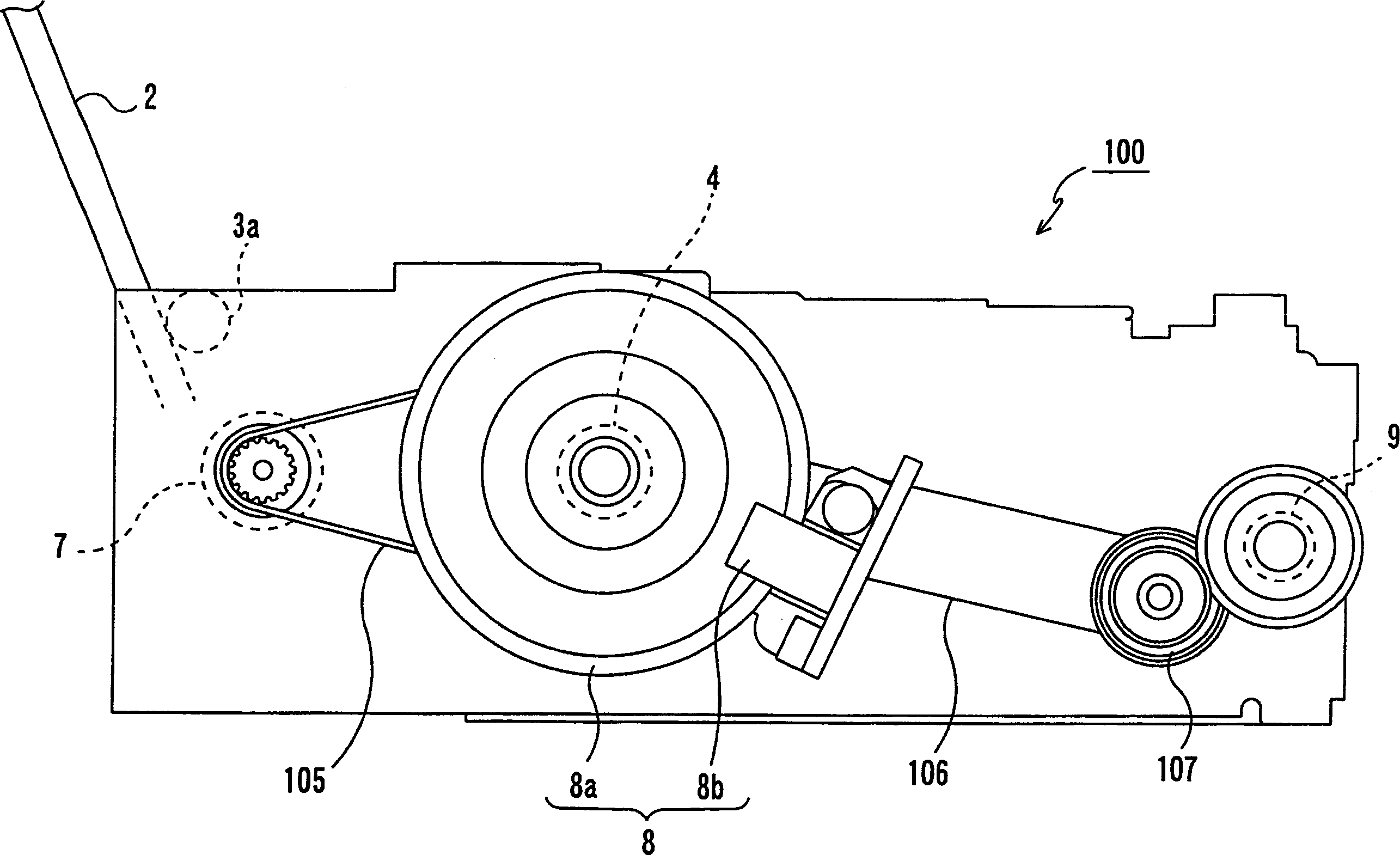
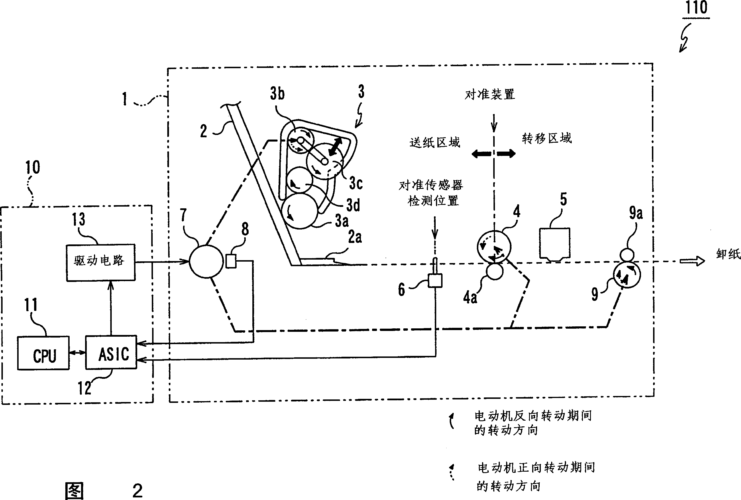
[0069] First, the figure 1 and 2 describe the schematic constitution of the printer according to this embodiment. figure 1 is a side view of the printer 100 to which the present invention is applied, and FIG. 2 is an explanatory view showing a schematic configuration of the paper feeding device 110 mounted on the printer 100 of the present embodiment.

[0070] Such as figure 1 As shown, the printer 100 of this embodiment mainly includes: a paper storage board 2, which is a paper storage unit for stacking and storing printing paper; 2; the transfer roller 4, which transfers the paper fed by the feed roller 3a during the printing operation; the unloading roller 9, which assists the transfer roller to transfer the paper during the printing operation and is unloaded after the printing operation paper; a line-feed (LF) motor 7, which is a rotation / drive source of the feed roller 3a, transfer roller 4, and discharge roller 9; and a rotary encoder (hereinafter simply referred to as...

no. 2 example

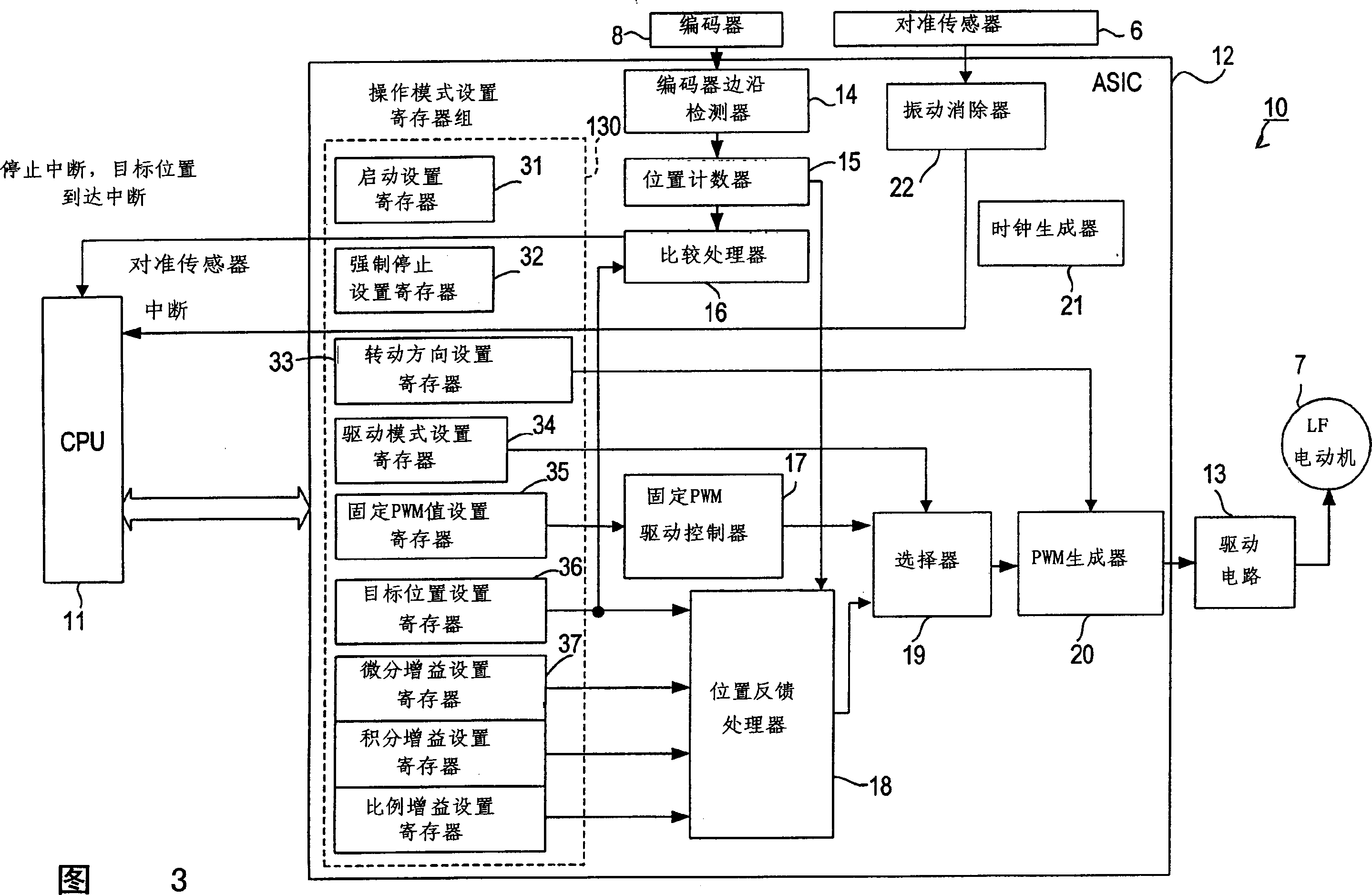
[0114] Fig. 7 shows a schematic configuration of a paper feed control device according to a second embodiment. As shown in FIG. 7, the ASIC 55 in the paper feed control device of this embodiment is different from the ASIC 12 of the first embodiment shown in FIG. speed feedback processor 47 , target speed setting register 41 , and gain setting register 42 . In addition, a cycle counter 45 and a speed converter 46 are arranged so as to acquire the rotation speed of the LF motor 7 (ie, the moving speed of paper) based on the pulse signal from the encoder 8 .

[0115] Another relationship is similar to that of the ASIC 12 of the first embodiment shown in FIG. 3 . Therefore, the same constituent elements as in FIG. 3 are denoted by the same reference numerals, and their descriptions will not be repeated.

[0116] The target speed setting register 41 configured in the operation mode setting register group 40 sets the transfer speed of paper (hereinafter simply referred to as "targ...

no. 3 example

[0127] FIG. 9 shows a schematic configuration of a paper feed control device according to a third embodiment. As shown in FIG. 9, the ASIC 60 in the paper feeding control device of this embodiment is different from the ASIC 12 of the first embodiment shown in FIG. The PWM increase coefficient setting register 64 and the fixed PWM driving controller 65 output PWM values ​​according to the setting values ​​of the respective registers 63 , 64 and the fixed PWM value setting register 35 .

[0128] Another relationship is similar to that of the ASIC 12 of the first embodiment shown in FIG. 3 . Therefore, the same constituent elements as in FIG. 3 are denoted by the same reference numerals, and their descriptions will not be repeated.

[0129] The initial PWM value setting register 63 arranged in the operation mode setting register group 62 defines a first PWM duty value at the start time of sheet feeding (separation). The PWM increase factor setting register 64 defines a method f...


PUM


Abstract

When the sheets are taken out sheet by sheet and started to be fed, in a first predetermined section, a driving mode is set to a fixed PWM driving mode, and a DC motor is driven in response to a PWM signal of a fixed duty to perform the sheet feed operation (S110, S120). When the tip end of the fed sheet is detected by a registration sensor (S140: YES), the sheet feed operation is once stopped (S150), and the driving mode is changed to a position feedback control mode (S170). Thereafter, the sheet is fed to a registration position by a position feedback control, the sheet reaches the registration position, the sheet feed is completed (S200: YES), and the process enters the next transfer operation. The transfer operation is also performed in the position feedback control mode. When a control method is changed before / after the registration sensor in this manner, the speeding-up and noise reduction of the sheet feed operation are realized.

Description

(1) Technical field [0001] The present invention relates to a paper feed device which takes out and feeds paper for printing stored in a paper storage unit one by one by a paper feed roller rotated by a motor. (2) Background technology [0002] For example, in a structure known heretofore as a paper feeding device mounted on an inkjet printer, a paper feeding roller is in contact with the surface of multiple layers of printing paper and is rotated by a motor to feed the printing paper in a predetermined direction. [0003] In this type of paper feeding device, a stepping motor is conventionally used as a motor for rotating the paper feeding roller. For example, in addition, when there is a paper feed request by input of print job data from the outside, the motor is driven to rotate the paper feed roller, and one sheet of a plurality of printing papers (stacked) is stored in a predetermined storage position. was taken out. The extracted printing paper is continuously sent o...

Claims


Application Information

Patent Timeline
Patent Type & Authority Applications(China)
IPC IPC(8): B41J11/42B41J13/00B65H3/06B65H5/06
CPCB65H2513/108B65H3/0669B65H2513/11B65H2511/20B65H2513/10B65H2220/01B65H2220/02
Inventor 秋山茂樹小久保雅俊
Owner BROTHER KOGYO KK
Why Eureka
Try Eureka