Rotary inverted pendulum

An inverted pendulum and rotary technology, applied in the field of experimental devices, can solve the problems of complex transmission mechanism, large floor space and low reliability, and achieve the effect of simple and compact overall structure, small floor space and improved reliability.

Inactive Publication Date: 2004-02-25
UNIV OF SCI & TECH OF CHINA +1
View PDF0 Cites 15 Cited by
  • Summary
  • Abstract
  • Description
  • Claims
  • Application Information

AI Technical Summary

Problems solved by technology

Due to the complexity of the transmission mechanism and many links, in practice, failures are often caused by failures or errors of

Method used


Image

  • Rotary inverted pendulum
  • Rotary inverted pendulum
  • Rotary inverted pendulum

Examples


Embodiment Construction

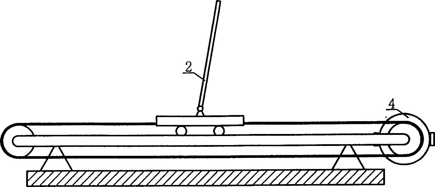
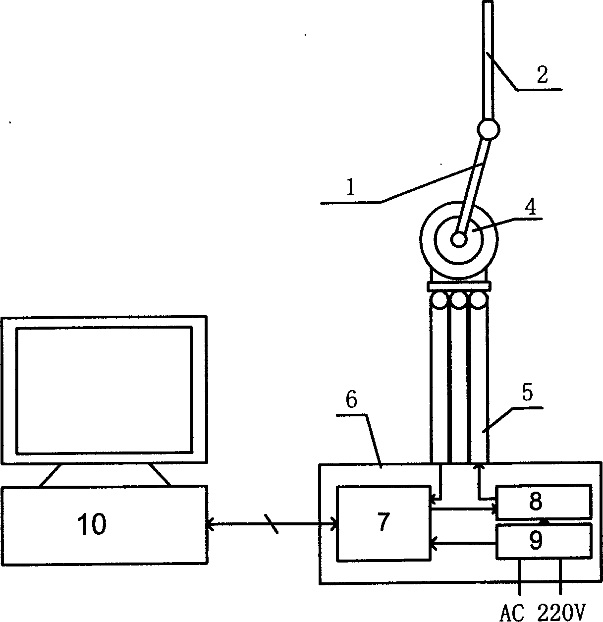
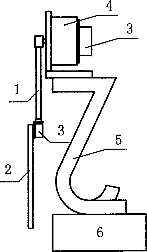
[0017] A specific embodiment of the present invention is provided below (but the present invention is not limited to this example):

[0018] The swing arm 1 and the fork 2 are all made of aluminum alloy, so that their own weight is relatively small. The bracket 5 is made of ordinary steel pipes; the motor 4 is made of a 70LY53 permanent magnet DC torque motor. The angle detection device 3 in the control system adopts WDD35D conductive plastic measuring potentiometer; the core control device 7 adopts the DSP controller of TMS320F240, which includes functions such as A / D and D / A conversion, filtering, and control quantity calculation; the external computer 10 adopts A general-purpose PC; the power amplifier 8 is a full-bridge pulse width modulation motor drive chip A3952. Arm size: φ15mm×200mm, swing rod size: φ15mm×250mm, bracket size: height 400mm, outer diameter φ20mm, inner diameter φ17mm, control box size: 360mm×240mm×90mm.

[0019] One end of the swing arm 1 is provided ...


PUM


Abstract

The present invention relates to a rotating inverted pendulum, belonging to an experimental equipment for teaching and scientific research. It includes pendulum bar, motor, driving component, supporting frame and its control system. The pendulum bar is connected with motor shaft by means of driving component, the driving component is a rigid rotating arm, its one end is fixedly connected with motor shaft and another end is hinged with pendulum bar, the motor shaft is horizontal, and the surfaces of revolution of the rotating arm and pendulum are vertical.

Description

Technical field: [0001] The invention relates to an experimental device for scientific research or teaching. Background technique: [0002] The inverted pendulum is an intuitive and vivid scientific research or teaching experimental device. In terms of application background, the stability problems of various objects with the upper center of gravity and the lower fulcrum seen in daily life, as large as the key technical issues such as the vertical launch of the launch vehicle, have a great relationship with the control of the inverted pendulum. similarity. However, as a controlled object, it is also a fairly complex high-order, multi-variable, nonlinear, and strongly coupled statically unstable system, which must be stabilized by applying powerful control methods. Therefore, the inverted pendulum control has become a very classic and challenging problem in the field of automatic control. Many new automatic control theories or methods can be analyzed, researched and verifie...

Claims


Application Information

Patent Timeline
IPC IPC(8): G09B23/06G09B25/02
Inventor 孙德敏王永卿致远张培仁吴刚
Owner UNIV OF SCI & TECH OF CHINA
Why Eureka
Try Eureka