

Ultrasonic wave precutaneous dialysis device
A dialysis device, ultrasonic technology, applied in ultrasonic therapy, dialysis system, treatment, etc., can solve the problems of high operation requirements, long treatment time, and long dialysis time, and achieve high operation requirements, short treatment time, and high dialysis efficiency Effect
- Summary
- Abstract
- Description
- Claims
- Application Information
AI Technical Summary
Problems solved by technology
Method used
Image

Examples
Embodiment 1
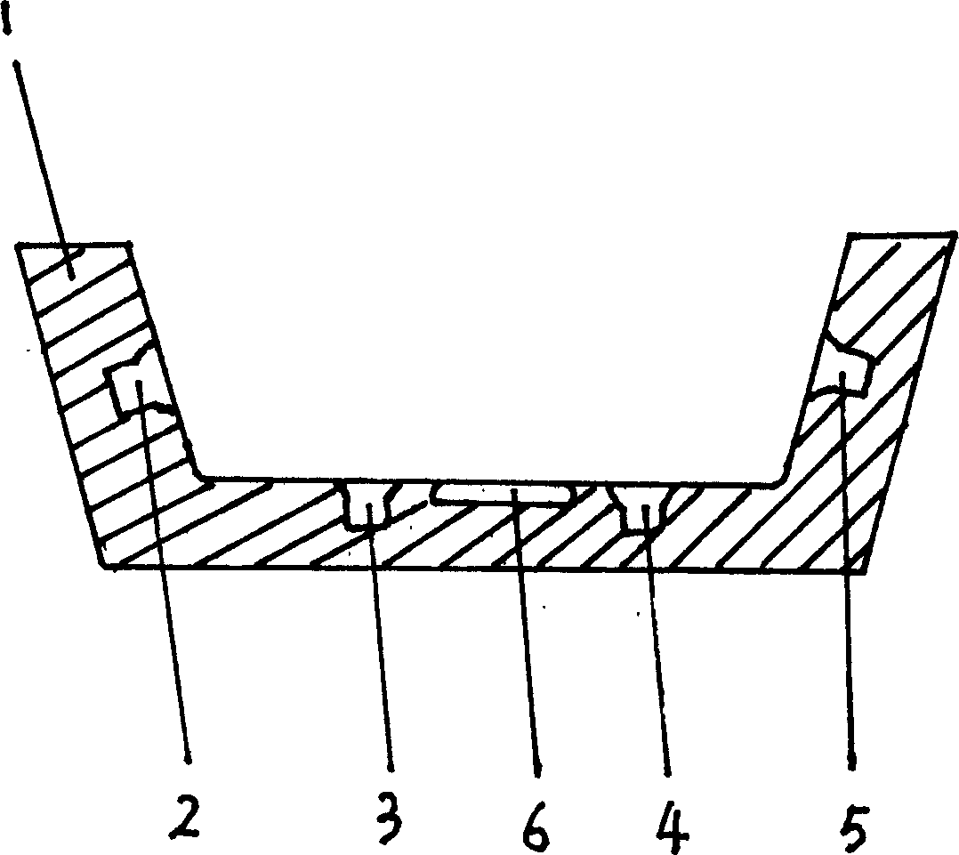
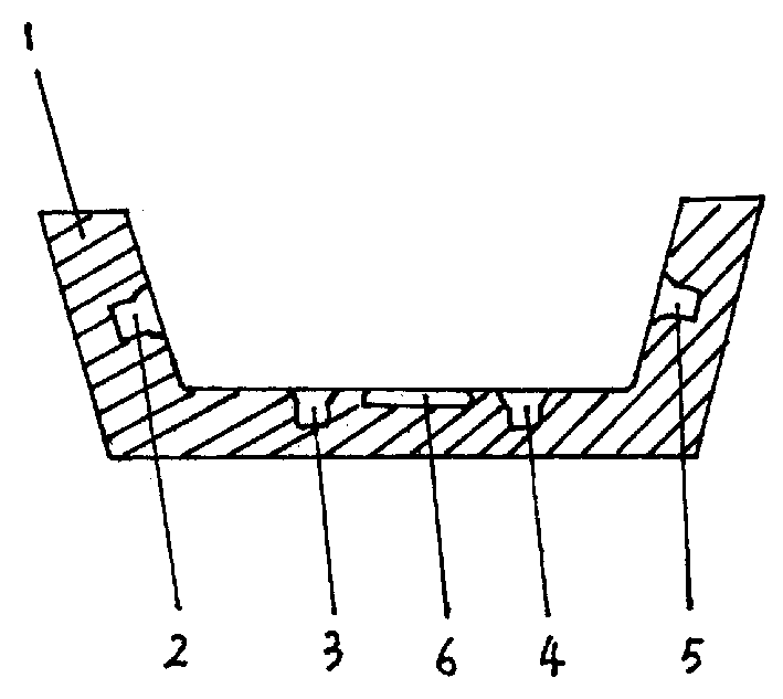
[0020] Embodiment 1: as figure 1 As shown, the present invention is mainly composed of a dialysis pool 1 and ultrasonic emitting heads 2, 3, 4, 5, wherein the ultrasonic emitting heads 2, 3, 4, 5 are arranged on the pool wall in the dialysis pool 1. When working, inject liquid medium into the dialysis pool 1, connect the power supply of the ultrasonic transmitters 2, 3, 4, 5 to make it emit ultrasonic waves, and allow the patient to soak in the liquid medium to perform dialysis treatment.
[0021] In this embodiment, the frequency of the ultrasonic waves emitted by the ultrasonic transmitting heads 2, 3, 4, and 5 is 20KHz-10MHz, and the ultrasonic intensity is less than 2.5w / cm 2 , the ultrasonic emission time is 30-60 minutes, and the temperature of the liquid medium in the dialysis tank 1 is 30°C-60°C.
Embodiment 2
[0022] Embodiment 2: In this embodiment, the frequency of the ultrasonic waves sent by the ultrasonic transmitting heads 2, 3, 4, and 5 is 0.5-1.5 MHz, and the ultrasonic intensity is 0.5 w / cm 2 , the ultrasonic emission time is 40-50 minutes, the temperature of the liquid medium in the dialysis pool 1 is 45° C.-55° C., wherein the liquid medium contains medicine.
[0023] In this embodiment, a heating tube 6 is provided in the dialysis pool 1, which can be used for heating and keeping the liquid medium in the pool.
PUM
 Abstract
Description
Claims
Application Information